• Don't miss out on all the fun! Register on our forums to post and have added features! Membership levels include a FREE membership tier.

GEN II, our home built snowbike project

M
Jan 6, 2015
1
0
1
37
Good day. I am very impressed with your work. After reading I had a desire to try to make a snow bike. I have a few questions for you. Can we talk?
 

christopher

Well-known member
Staff member
Lifetime Membership
Nov 1, 2008
81,519
27,382
113
Rigby, Idaho
JUST A NOTE

In post #1 there are 54 Embedded Images.
Only 5 of them are being displayed, and those are HUGE for this forum to display!

The other 49 all point to a URL that says "Content not found"

If the original poster would like everyone to be able to see those images, it would be best if he uploaded them directly to his SnoWest Photo Album, and then embedded back into this thread
 

swedenturbo

Well-known member
Lifetime Membership
Dec 4, 2009
330
397
63
Sweden
Sorry all visitors here for not showing you all photos of the buylid process. Sad to see that pics are not shown.
Many photo URL's in this thread was linked from our snowbike build group on Facebook.
FB has unfortunately changed most URL's

Since these photos pics didn't show, all recent post were made by using Tapatalk. Seems more reliable in this matter.

Christopher: If I want to edit old previous posts with new photo URL's, is this possible?
 

swedenturbo

Well-known member
Lifetime Membership
Dec 4, 2009
330
397
63
Sweden
Reposting previous post, now with working photos

Hi guys!
This gonna be a long first post but I´d like to share our progress so far. Hopefully I will post you more as we go...
I think photos tell more than plain text especially when I work hard to write in english ;-)
Hope you enjoy my pics ;-)
Seen lot of DIY snowbike kits here, great work guys!


2 years ago, me and my buddy built two Mountain horse replicas, well it may look like a copy but we designed it only from pictures seen on the web.
We didn´t dare to build the suspension so we used a MXZ skid. An easy way out but doesn´t work as well as the original suspension.
Here's a link to some photos of our first build.http://www.snowest.com/forum/showpos...79&postcount=2

We have ridden with it for the past two years an it works pretty well.
There are some things we would like to improve. Instead of motifying existing kit, we took the decition to build new kits.
Things we saw could be improved:
1. Less weight. We aim for a weight reduction of 15 kg, hopefully more.
2. New suspension. The build used a modified MXZ bogie , greatly oversized snowmobile suspension that is basically for hard trail riding. Instead we plan to build a pure snowbike mountain suspension . It will be much lighter and designed just for snowbikes, not sleds.
3. New track. Last track was 3050mm with 44 mm lugs. The new build will use 3460 with 59 mm lugs. As we ride 96 hp turbo bikes, we believe they can pull that track easily ;-)
4. New tubular frame. The first build had steel tube with 2 mm thicknes, way too heavy. Now we´ll use 1,2 mm thicknes. A Swedish steelquality called SSAB Docol. Its reminiscent of chrommolly but promises to be easier to weld and less risk of cracks.
5. Movable jackshaft. We had some issues with the tension pulley on the motor chain. Moreover, it has been difficult to get the right chain tension, especially with some gearings. By being able to move the jackshaft equal when tightening the chain on a motorcycle rear wheel , we will be able to run any kind of gearing, less parts and also lighter .
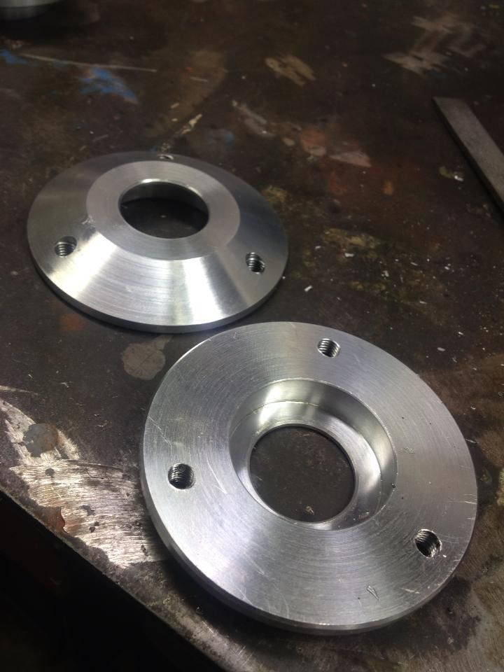
6. 6005 bearings with updated custom made housings. Less weight
7. A slender and more sturdy chain case that reduce the risk of hitting rocks and stubbles.
8. Newly designed tunnel panels that are more slender and exposes the track so that any stubs or rock collisions are hit by track and drive wheels and not the front tunnel area and chain case.
First challenge is the design of the bogie.
We will try to design a suspension similar as EZ ryde. Believe that it is passable for these machines with good options to adjust ski pressure and suspension stiffness. In addition, the EZ ar well known for its good powder snow properties.

Started by cutting the 59 mm track. A really crappy job, but what do you do? Smokes and smells like hell but at the end a good result.
The reason we start by cutting track is that we want to strip that is left.
With it, we will make a simple mockup of the suspension to try different geometries.
21fc0f675e92823d9ef724dae372f879.jpg

01e1ddc0e3244dc765805b79e3925560.jpg


14f27191fdca930700f1e91e789e7349.jpg

As said the GEN II will have a new custom designed rear suspension.
We begin with an analogue "drawing" to test geometries.
By doing all out of wood and chipboard we can easily test various attachment points and see how it affects the suspension travel.
We're onto something, but need to adjust some attachment and get a slide function on the swingarm rear mounting.
Unfortunately, this type of bogie has an "impossible geometry" of track tension and, therefore, the sliding function combined with the front shock will push back the rail
therefore tensioning the track. Have done shockdummies with the correct length and stroke.
We also printed the blueprint from our first build at a scale of 1:1 to get some known references.
That way we can see how our analogue drawing will fit the new design.
We try to be thorough with the design and all the drawings.
This way we can order most parts pre-cut with almost every drilling done.
e413119be645e0516a0a49db9993fa8d.jpg


The first build was more or less a replica build of original Timbersled Mountain Horse. Here´s the new design of the tunnel panels.
Looks similar to the previous build but is completely redesigned.
attachment.php

The bogie will remind EZ-Ryde's design.
We believe one advantage is that it is completely uncoupled and enormously lighter than Ski-doo SC4 suspension.
Also, the front of the rails will hopefully flex in a way that can be beneficial on snow bikes.
The rear travel is more than 400 mm.
Here we test the suspension travel more theoretically.

83cd215abbeab6e6f2616b0435ff5465.jpg

EZ ryde on sleds have a swingarm that can go almost straight back. On a snowbike the swingarm has to move into upper bogie wheels due the narrower the track.
If the swingarm would go straight back without a waist, it would be in the extreme compression hit in the bottom of the upper bogie wheels.
For that reason, the swingarm to get a little odd design.
1292825_10151635352602672_1622084462_o.jpg
forum


This image shows better how the upper bogie wheels sit in relation to the swingarm.
1278103_10151636719267672_433390437_o.jpg

Yes, finally all the laser pre-cut parts and done! Here we go! Many parts .... All this for two kits + one set of welding jig.
f71b016464564b03e8fff37ee53db253.jpg


These parts are cut out of 3 mm steel, made for just templates for jigs.
c80a9656b28dad1f27a25ec279ce3f82.jpg


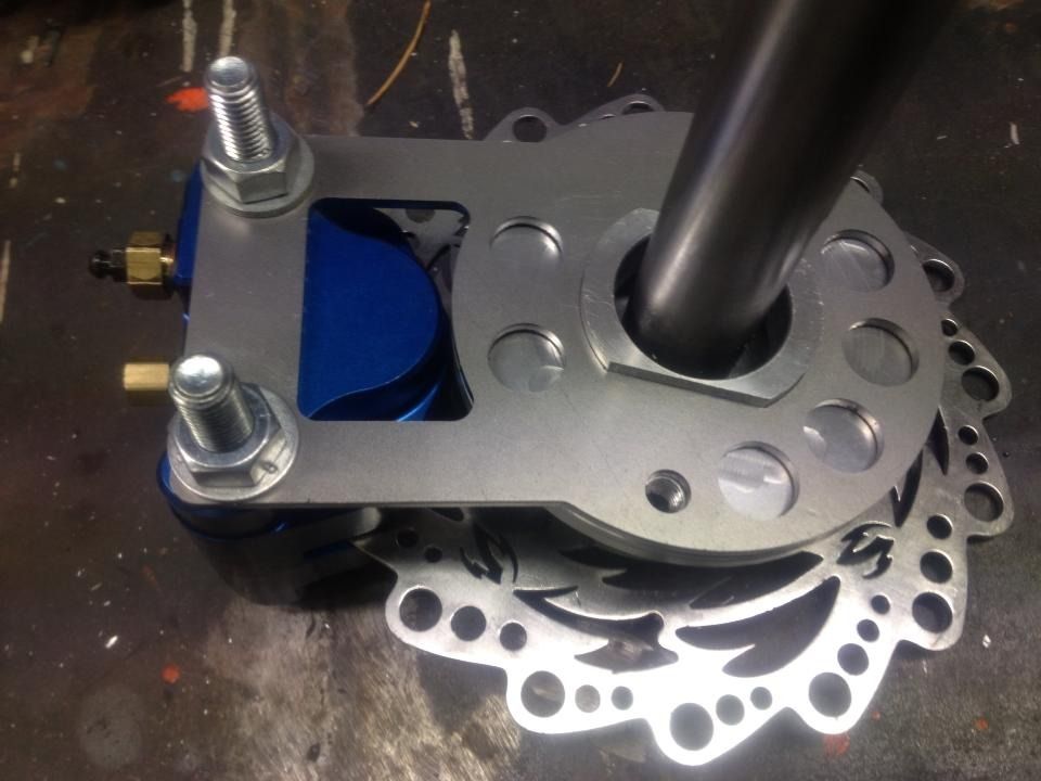
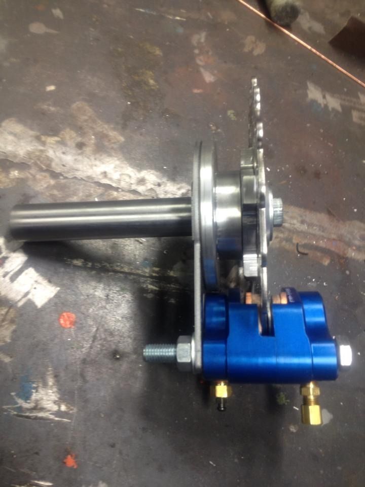
Here you can see some of the design in the movable jack shaft. As the shaft are moved, the brake calipper mount also moves.
30d6bb04893e397e6e84d69b503161b7.jpg


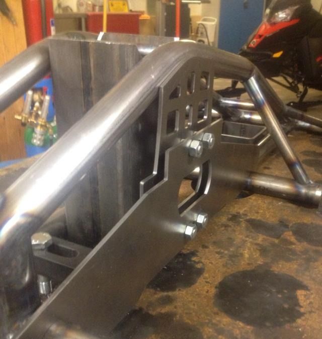
There are some differevces in the design between the first build and the GEN II. Side panels are of a more modern straight lines and kind of duck tail ;-)
191924206293c3e7af4f7af89b56c796.jpg


Starting to work with "the mother of all jiggs". Spent some time on it but we will regain that work later on.
This piece is thick and heavy and stands up against anything! Laser cut drilling template facilitates that the attachment points will the right place.
May seem a little over-ambitious, but but it will help us in the long run ;-)
I would highly recommend to order precut jig templates. We feel confident that all the measurements are correct and that it is straight.
1116002_10151733915732672_1873529628_o.jpg


0e45845da2c664291fdce123c5f124fb.jpg

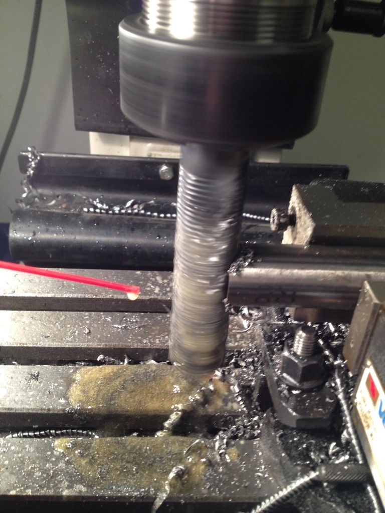
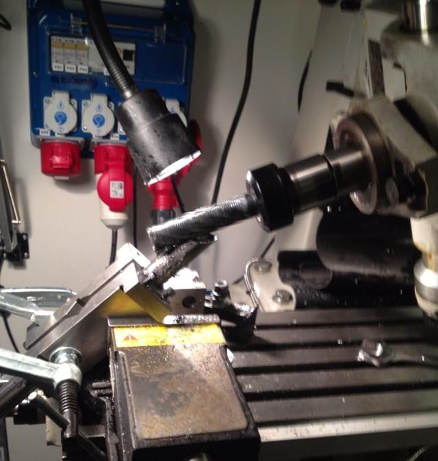
Tried some notching with the mill.
1401544_10151735656407672_1429278099_o_zpslc5qqpjq.jpg

1401814_10151735656082672_1019722562_o_zpstmjuvv8h.jpg


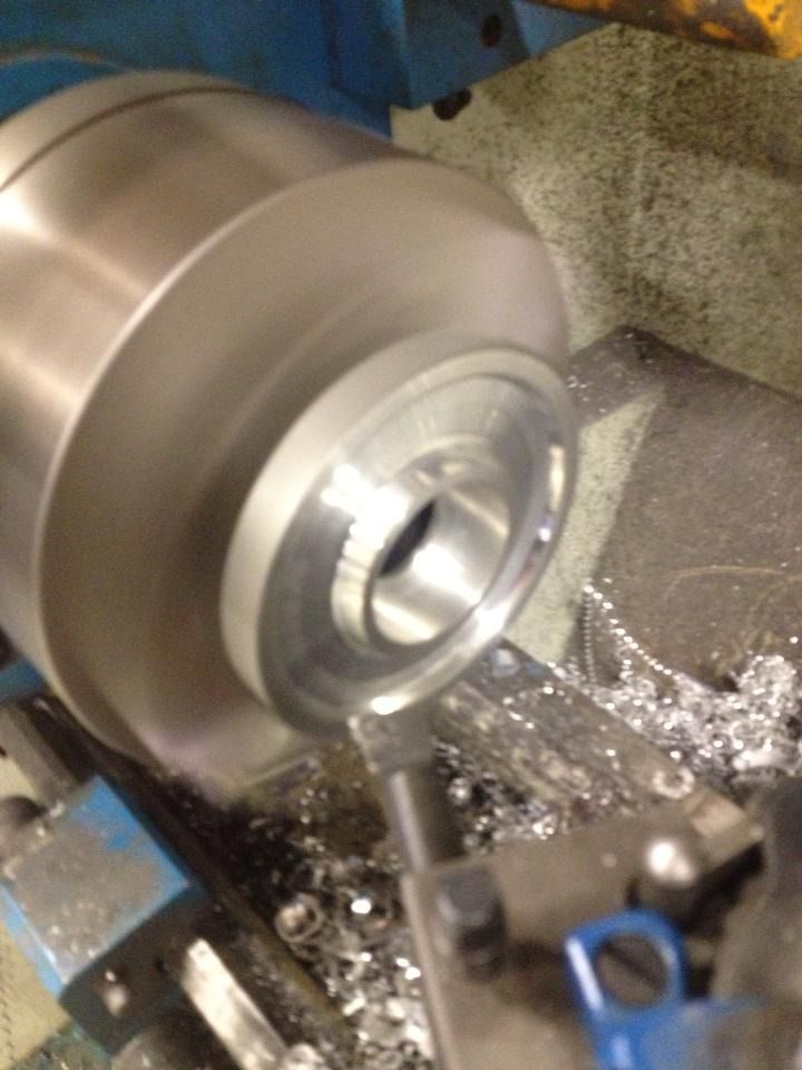
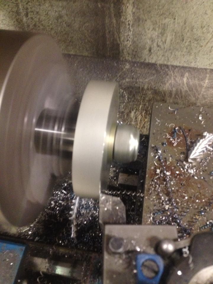
Lathed and milled the upper bogie wheels. They will have a diameter of only 100 mm.
999993_10151765100707672_1779467680_n_zpsrx3qc08m.jpg

1382366_10151765100402672_1896792719_n_zps2msgyskq.jpg


1390781_10151765100217672_1724868296_n_zpsihepwrmw.jpg


This time, we ordered pre-bent tubing to tubular frame and swingarm. The drawing was of great help to get all the measurements and angles right. The swedish dragracing frame company ME-racing has done a good job of bending. Fits correctly!
1399019_10151733910507672_1823968345_o.jpg


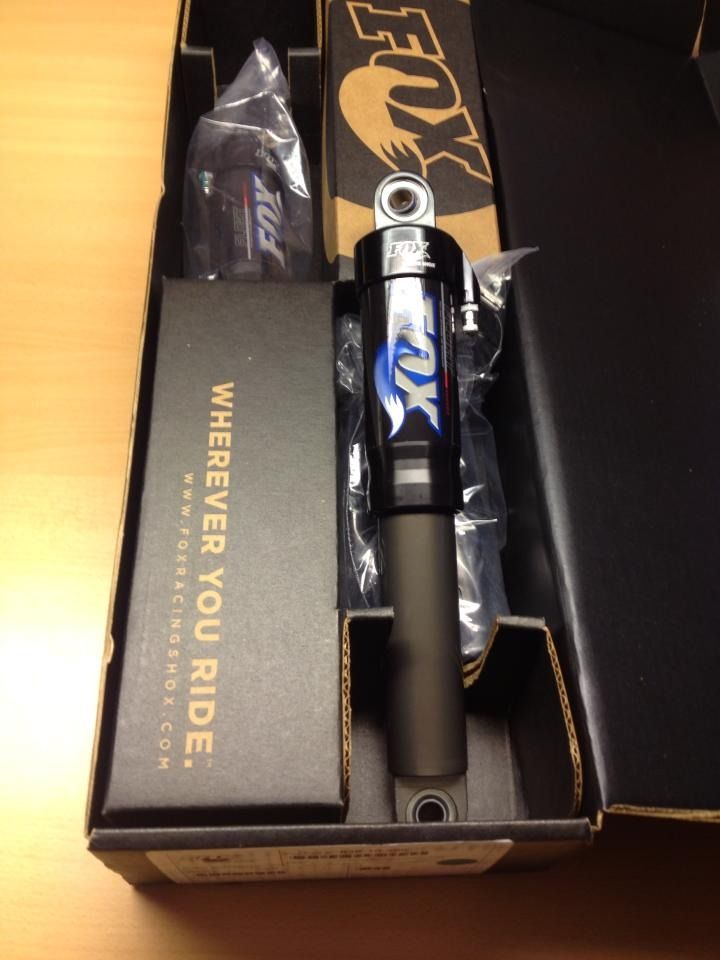
Ordered the front suspension FOX Float shocks. They are originally to a Honda ATV for correct length and stroke 330 by 259 mm.
1381588_10151764650847672_931276891_n_zpsasufvjal.jpg

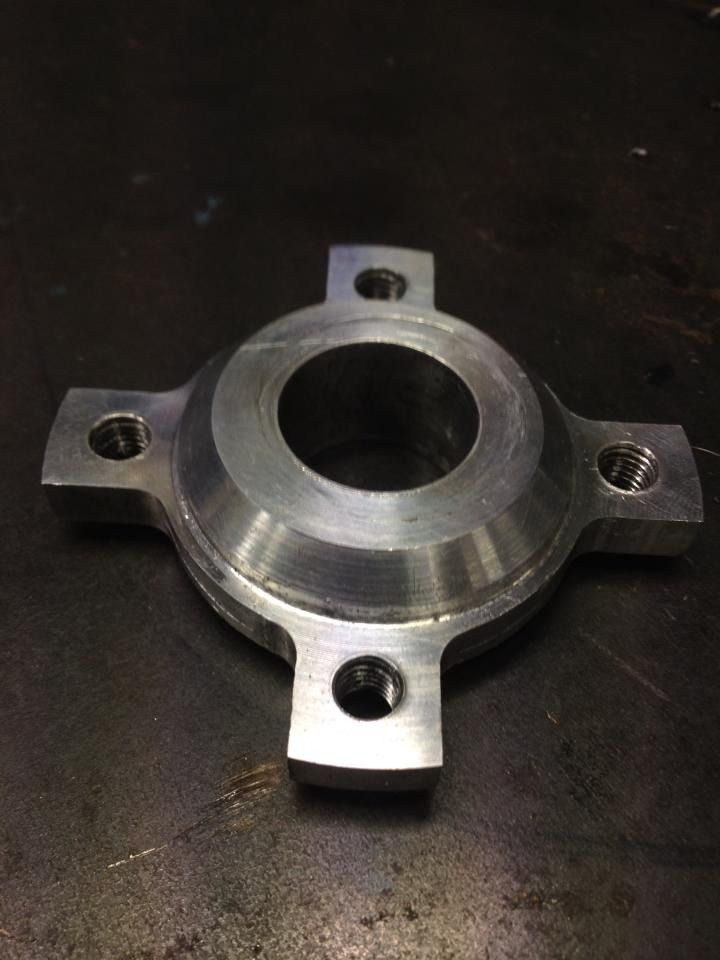
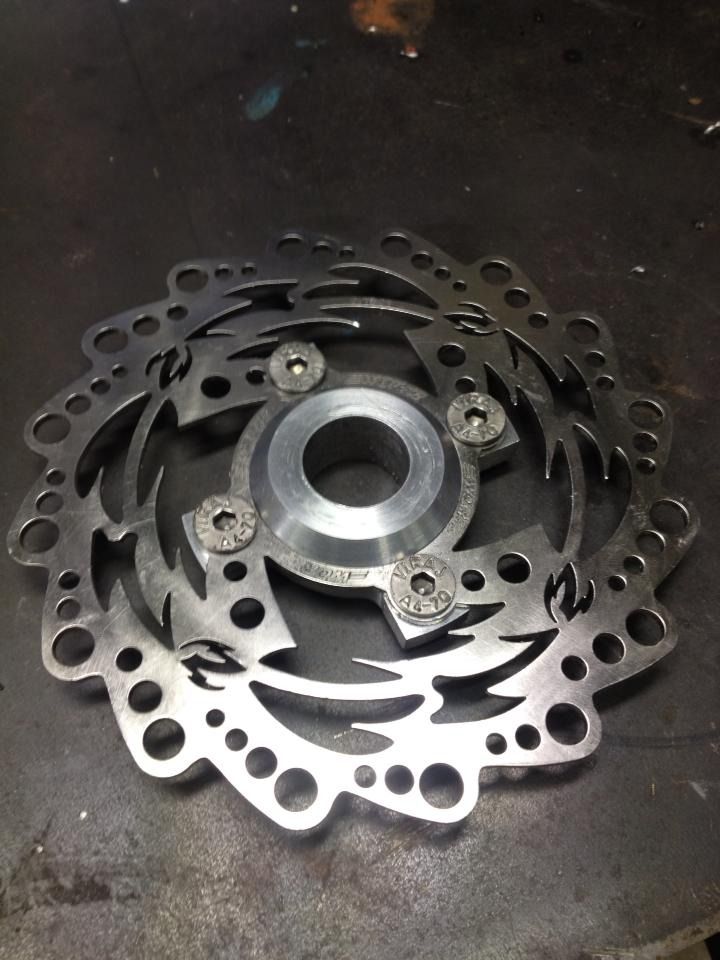
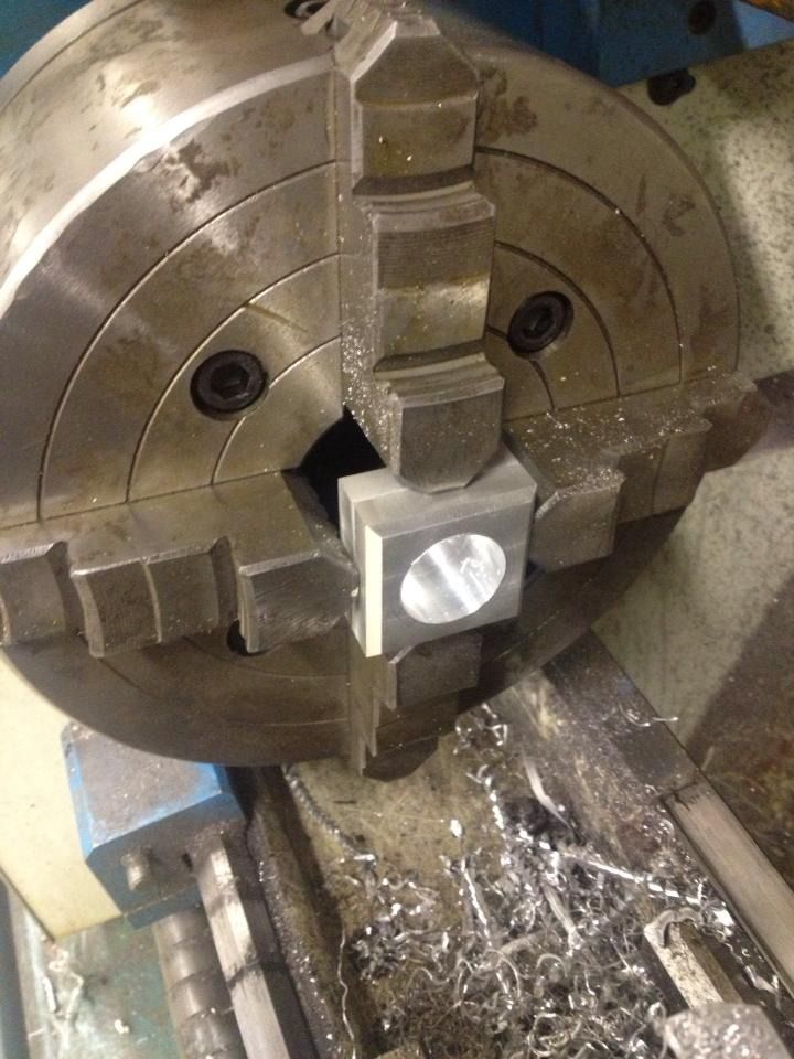
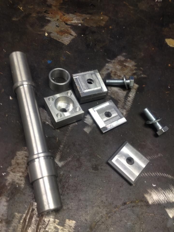
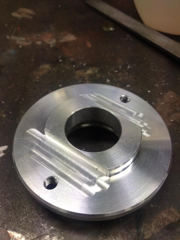
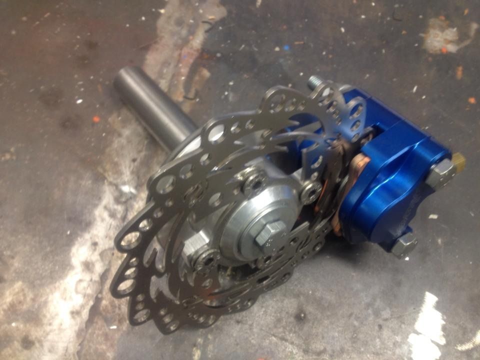
Lathed and milled hub of the brake disc.
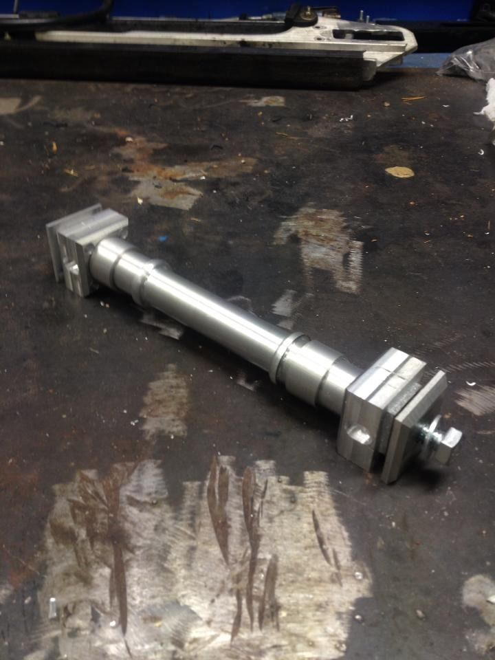
1391677_10151778331727672_888913307_n_zpsvugnptoi.jpg

575753_10151780871742672_412924885_n_zpsl6awvhzf.jpg

1426131_10151780871467672_1355443996_n_zpsjz0inrda.jpg


1450858_10151780871332672_115588575_n_zps4j3feiqc.jpg


Made the rear axle.
1459184_10151793457552672_790278541_n_zpsqr6mvn9m.jpg

945462_10151793456397672_1695570608_n_zpsd1hgcsdk.jpg

1452496_10151793457027672_1919281837_n_zpsfojszwjm.jpg


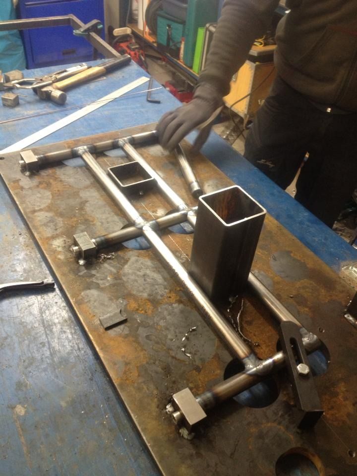
A little start with the tubular frame. The fit seems to be better than expected.
1465265_10151789599497672_1355899796_n_zpstmkgwji8.jpg


1441417_10151789509442672_998484201_n_zpsk9akhhao.jpg

A little work left on the drive shaft as we await delivery of the drive wheels. The gearing may be a bit unusual : 14-19-18-16 give a final speed of 91 km / h at 8,500 rpm at 5th gear. 6th can be considered as a cruise gear.
If gearing will be too high , we can easily switch to 17 or 18 tooth on the drive shaft .
927b3fe6f59128f8e74f36a224207192.jpg

8986ec1b755acd1a8a8a5fc9d3cd463b.jpg

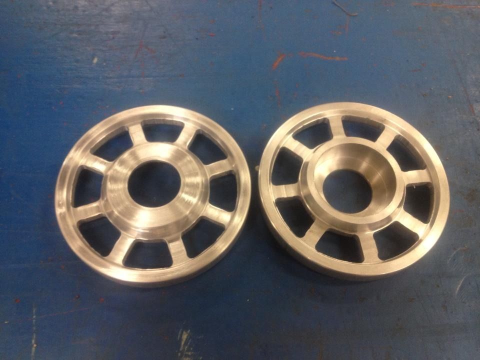
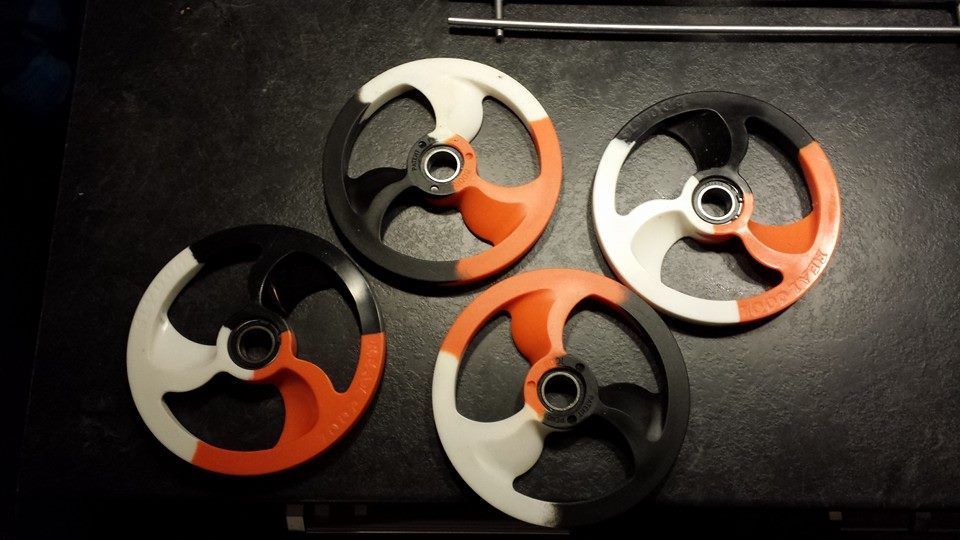
We want the sprockets to be as lightweight as possible .
Started with a simple drawing to get the right dimension spacing of holes. Want to be a bit careful with the holes so no strength deteriorates.
"Spoke" thickness is 8 mm in small, ranging between 9.1 and 5.9 mm on the large gear with large center hole.

5adaf96e16be6a925e76eae3b73f448d.jpg


eec8a05ed00c50d1ee1cd16cf8d95a5a.jpg


Partition table is a big help to drill the holes with correct spacing.
47adcda270ea610fc2f56cda92a4c7a1.jpg


The sprockets seems to be as strong as solids. Total weight of all sprockets incl. clamping sleeve on one sprocket was 1,007 grams.

5424daaf4f5410662b938ecabb66276c.jpg


Here is the drawing on the drive shaft and jack shaft .
1415083_10151804985742672_297848321_o.jpg


The shafts will be drilled with 16 mm long drill.

8" Slydog rear wheels weighing 350 g. Of course in KTM colours ;-)
forum

1461063_667871719913557_895500629_n_zpsl8paywyo.jpg


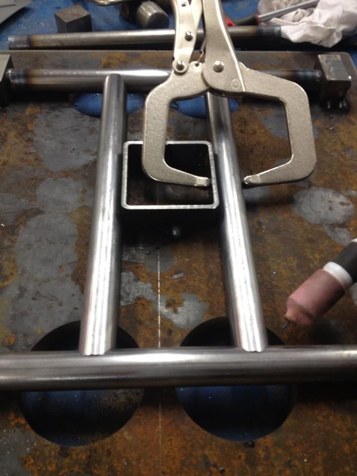
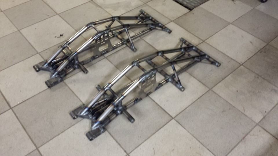
The work with the first tubular frame proceeds. A little work left before we can remove it out the jig. It will be interesting to see if it warped after welding.
b6ecc3e914582b3757bf149249928440.jpg

fab5a6d82843bcd553858343150decab.jpg

1421097_10151809910192672_214433251_o.jpg

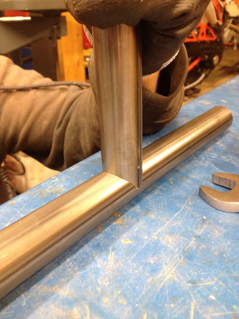
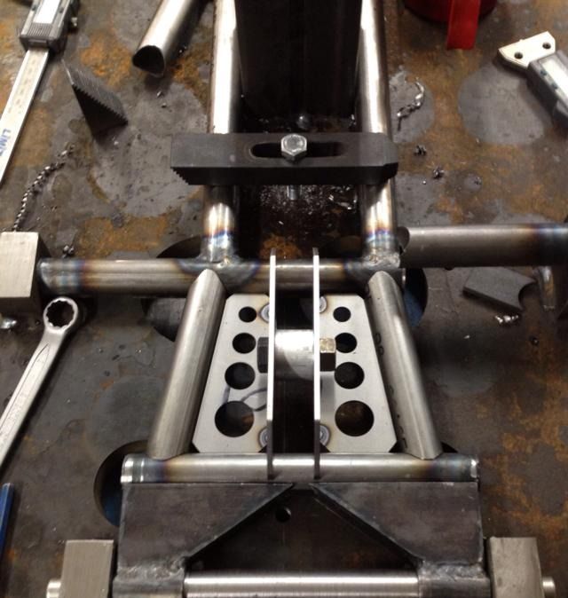
Notchning of the rear connection of the arch was improvised. We clamped the pipe at 45 degrees and then tilted mill head 67 degrees for it to be the right angle. The results exceeded expectations.
1461759_10151809915727672_1148647566_n_zpslnijshpn.jpg


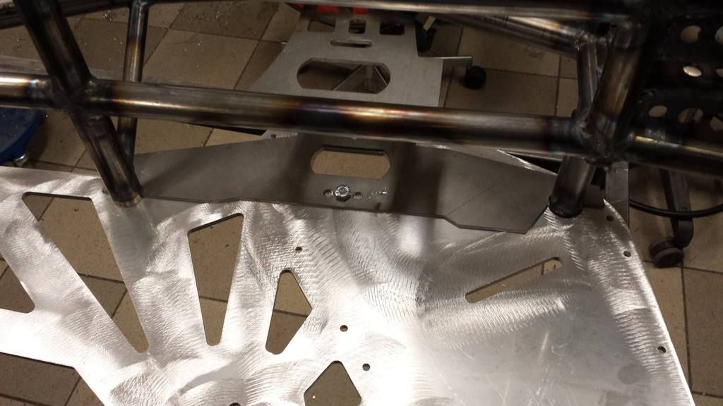
On this kit we ordered precut base plates, of course, with lightening holes.
530326_10151809917277672_2112361311_n_zpsvlshozy9.jpg


The holes in the jig was made ​​that we can turn it upside down and weld the bottom without having to remove the frame.
Anything to prevent warping when welding.
cc5350b275b9fe86ff29598883b90e93.jpg

5f178d94cf3ae6d288c4ef0c1d465bfb.jpg


340bbd1fd7c719a0295c81171666f916.jpg

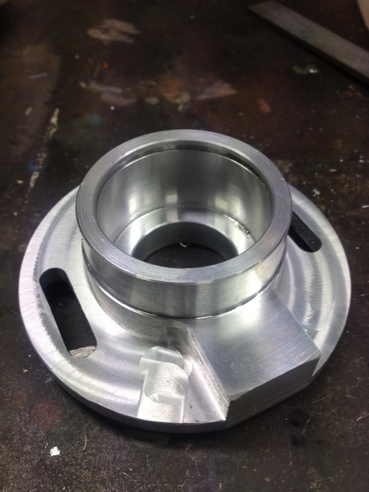
The last build we used a cut off Ski-doo REV-spindle in the lower part of the ski bracket.
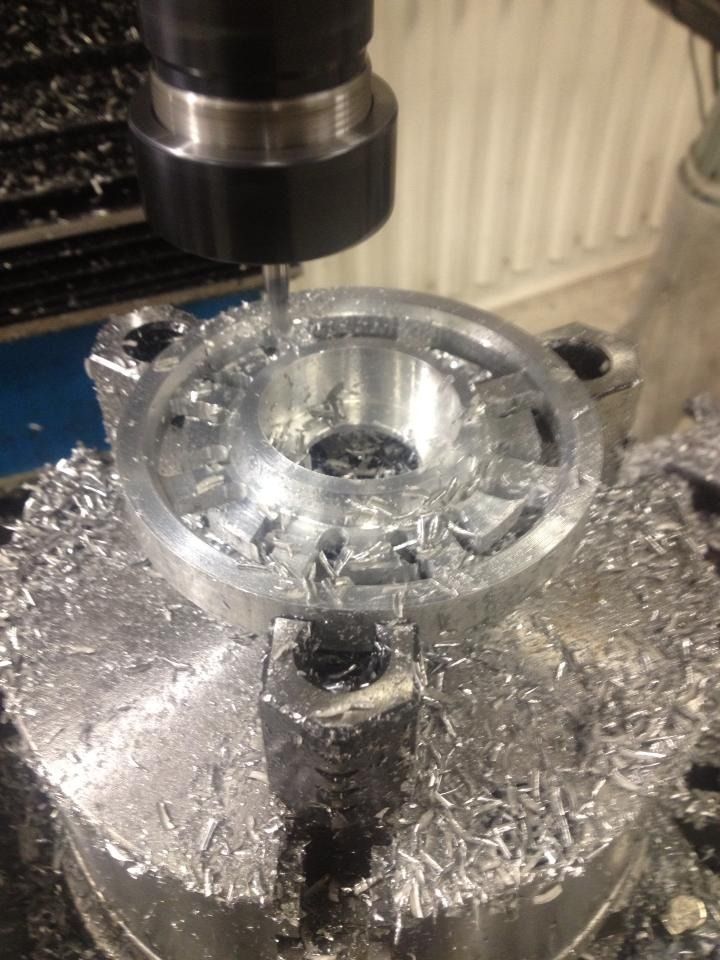
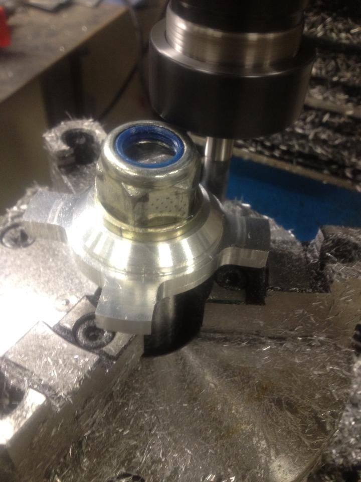
Clearly the easiest thing to do for the home builder but this time decided to make it a bit more advanced made out of billet aluminum.
531a96d9f160cebd20ea63c210234372.jpg


Started by making a drawing to get the coordinates and angles .. The material is a circular block with a diameter of 100 mm.
efcadabf65f6fd0e65c788269e0f3a15.jpg


Lots of material to be milled ...

444c64f60bb37e8bac4f9cde06cb4f16.jpg


Round feeding table made ​​it easy to get the right angles. Hole drilling seemed to go as planned.
8e5dacd473f609f588a616821be17a7b.jpg


The outer round part of ski bolt bushing was kept while the rest was milled around using circular feed table.
76d2855a92a98256e3d4b1c435773418.jpg


0d5cd2121b9587e68f1d1ea5ebf8a2be.jpg


95f215c36e9ba44d349027a0e2448d84.jpg

Edit:
Forgot to upload the final overview drawing:
1264862_10151721918587672_652678981_o.jpg


More to come....


<!-- / message --><!-- edit note -->
 

swedenturbo

Well-known member
Lifetime Membership
Dec 4, 2009
330
397
63
Sweden
CNC machined housings required little further milling, drilling and tapping but now they're finished!
50c4af8a8c324bb78bf9c900e4f5b190.jpg

This bearing housing will sit on jack shaft closest to the chain case. Has dual 6005 bearings as this will be under double loads. Partly from motor chain and chain in the chain case. The saved "block" is where the tensioning bolt will push.
1468635_10151828063472672_6007052_n_zpsky3gcinb.jpg

The back is milled to run in the slot hole in both tunnel section and the tubular frame.
1458552_10151828066552672_355308155_n_zps5kfbxrup.jpg

Drive axle housings have no locking ring groove as tunnel panel holds bearing in place.
1477940_10151828068887672_559868165_n_zpsw99dzjpk.jpg


Here you see the principle of chain tension by moving the bearing housing.
8dfe28fbaa6fecb669108112e23e919c.jpg


A small drawing error. The radius of the hole in the tunnel panel does not match the radius of the bearing housing. Gotta grind this to get it right.
10437df169ca0a473e03f4393ee60ec3.jpg
 

swedenturbo

Well-known member
Lifetime Membership
Dec 4, 2009
330
397
63
Sweden
First frame completed. We are pleased that it hadn´t warped during welding and was completely straight. The jig must have prevented this in a very good way. We had predicted a weight around 5 kg. A little disappointing that the scale showed 5.4 kg. However, we believe that this frame is stronger. The reinforced swing mount sleeves adds a little weight.
883227_10151825855227672_713822392_o.jpg


Here you see the laser cut template which is temprary bolted to bearing housing mount plate. This way we can ensure that it´s welded in exactly the right place. Same template will be used when we drill the mounting holes on the tunnel panels. Just to ensure that both bearings will be alligned correctly.
893950_683326408368088_623900520_o_zpsv7yordyn.jpg


1463344_10151825883002672_961744514_n_zpsed3x4xft.jpg


<!-- / message -->
 

swedenturbo

Well-known member
Lifetime Membership
Dec 4, 2009
330
397
63
Sweden
We try to make every single part of the kit as light as possible.
Drilled the 27 mm drive shaft and and the 25 mm jackshaft with a 16 mm long drill bit. If there has been a 270 horsepower engine, the shafts probably wouldn't hold up but with a 50-100 hp snowbike it´s a different story.
We plan to temper all axes to further increase the safety margin.

Machined a plug in 16 mm the hole at each drillhole end of the shafts.
Then drill a smaller hole and tap for a M10 bolt so we can pull the whole assembly together at each ends of the shafts.

Machined the plug by two hundredths of a milimeter oversized for press fitting.
927b3fe6f59128f8e74f36a224207192.jpg

The plug welded, shaft end machined and tapped.
8986ec1b755acd1a8a8a5fc9d3cd463b.jpg


Right side if the kit (shafts turns clockwise) is threaded M10 fine left hand thread. Left hand threaded should hopefully reduce the risk of it coming loose, even without Locktight.
4a3ed943dd240940d8a604eb7d2f7343.jpg

Testing assembly of bearing housings, brake caliper mount and caliper.
As the pic shows, the bolts are too long, need to fix some shorter....

1463047_10151832214967672_867012310_n_zpsmtsbfc1s.jpg


1465135_10151832216307672_592340991_n_zpspn8s01ne.jpg

1468653_10151832213127672_1052424466_n_zps9h9v0eo3.jpg


Here´s the drawing of our shafts.
1415083_10151804985742672_297848321_o.jpg

<!-- / message --><!-- edit note -->
 

swedenturbo

Well-known member
Lifetime Membership
Dec 4, 2009
330
397
63
Sweden
After a lot of TIG-welding the frames are completed. They didn't warp after welding so the theory worked in practice.
1453402_680363351997727_1071441502_n_zpslwtc3wru.jpg

The strut replacing the rear shock completed. First build, we had a solid 30 mm aluminum rod. This build we try to make it as light as possible by making the strut hollow. Almost exactly 0,2 kg less. Now weighs exactly 0.5 kg. Worth the effort? Well, maybe ....
27a6929964ca698142e20900bfc2063d.jpg

A drawing of the strut.

411b3e131c590290d22b3e0e9c979292.jpg

30 mm rod drilled with 22 mm drill bit. Welded ends machined and threaded.
019f3cadda6a472b543625ae3273a787.jpg

Bent the side panels of the ski mount. We will produce 4 units, 2 ski mounts per kit. Good to have an extra if we'll unlikely wrecks a mount.
304197c3202bb7e6bf57ba5ed218a67c.jpg

When you have no bending machine, just fabricate your own for your tool press
fcb702ed72609380ba619cf51c74f9dc.jpg

9b81829ec540aadf84e22ec6e059bfb8.jpg

Works really good!
7c9c68e8e7e90aaa5d2917dfd15d390f.jpg


The cardboard templates gets the bending angles right.

925399097041f5a0fde3cb8087226be3.jpg


Machined axle sleeves. The edge goes inside the aluminum panels, welded both from the inside and the outside.

89dca7b073e183873f2c6d3fabdde5e1.jpg


Made a wooden template to bend the strip that will form between the side plates.
c4f07b3b6c2bee24cb2993d0b9d48bad.jpg


Welded inside before the strip were attached.
forum
b465c2af2ca192f94eff0fb2c91154a7.jpg

97c5b7ad85aadb4a93ac64b2a65fb637.jpg


eaf5675d05d2818ba0f926ffaa3233f3.jpg


First test assembly of the side panels and tubular frame.
087c3936ab804cb3f401954b9cbb8e61.jpg


The laser cut template was also used to align mounting holes for the side panels. This we think this is crucial of the alignment of chain case bearing housings.
479a1300fe9a8e74d36a5346600be165.jpg


ff96d111c3e8721efeb28a8b3c63820e.jpg
 

swedenturbo

Well-known member
Lifetime Membership
Dec 4, 2009
330
397
63
Sweden
The work om our build proceeds.
0aa19353120362f1f613391c3d9ecaa1.jpg

8dbd4fb24e3a9a26c61682a5a7e46f88.jpg


Machined bushings and shaft to the front attachment of the swingarm.
134db200c149a4501516f80fc1c7c2d7.jpg


The first drive chaft we made of hexagonal rod was sent to the scrap box. We have discovered that the steel quality was too low and threatened to break.
Machined a new drive shaft. 32mm shaft of machine steel in good quality. Shaft diameter 27 mm and drilled out with 16 mm long drill.
e15c8658b90f16187ffae384c56d6913.jpg

58fadfaf5a371f5de64e69d45e8363d6.jpg


6cfb647e6e470ea2d0e3761d4d10549f.jpg


dd8ae20069f8a72e9175d96b9a9a0ebf.jpg


Skid and suspension completed.
Rail extensions are nt light weight or pretty. Will run these during testing.
I have some longer rails from a Nytro that I will test when the kit is completed. I Think the Nytro rails has a better design for the LT application.
ST rails and track might be a nice option for the spring season!
061a28fd0d450e834ed8d523a1ee9957.jpg


0eb69a45f2237e36ef2ba9cd60f79a76.jpg


Made ​​the chain case reinforcement rim. GEN II will have a different solution to the chain. A 10x30 mm aluminum rim bolted from the inside of the tunnel. This will stiffen the tunnel panel and we think this is much better compared to the previous solution on the first build. The chain protection lid will only be a thin sheet that covers the chain.

b6391fa85064bcc9ca8d37b65d910a79.jpg

A laser-cut folding template made bending easy and accurate.
0aafa8b91be138504dda84bf59c9dea9.jpg

e1b8db7ee3c918386c8349fd54732ba1.jpg


Both sides of the rim was milled flat.
881b3f8c07e6571a2431899bcefd378d.jpg


Another drilling template makes the holes will line up correctly. Tapped for M6 screw with countersunk head.
df8dd1a7e4a8da41cd6f80f31cf084bf.jpg


The rim will have a small notch so that the lid will be flush.
34e324e982c9dc11b922c7a0903a3677.jpg

7c556a5058ebc9dcf6acd35d2256d674.jpg


6d6582256b3837523973ec28fd8d1d2c.jpg

1b5d9b4cad6530619f0fce0edbae3cbc.jpg


Test assembly. Only the middle bolt hole is pre-drilled in the tunnel section. This is to be able to adjust the position of the other holes that is bolted to the tubular frame and the jackshaft is aligned. The previous build we had some problems when the frame warped during welding. The predrilled holes didn't line up and we had to grind them up to get it right.
e8d3fcc333c3cf64b690ee29df65a1bf.jpg


ad28d1bb6f36469b30f66d4c4bebaedc.jpg
GEN II will tension motor chain by moving the shaft.
The caliper is mounted together with the bearing housing so this will also move with the jackshaft.
f24a346c57864903b7e174e98e3daf9b.jpg


e88f848de81fc73afaf6a4c13e072349.jpg

79ba3b00a1b322f393ea2c76722e83cb.jpg

af11f12333f52180dc595c4a007419b3.jpg

<!-- / message -->
 

swedenturbo

Well-known member
Lifetime Membership
Dec 4, 2009
330
397
63
Sweden
First test assembly of suspension.
It may look tall standing on the workbench without track but in fact it is just 40-50 mm taller than our previous build.
Tunnel is shorter than the bogie and will have a snow flap in rear.
bb6117cf9b63f416f16d956f2e7ac148.jpg

de7e6dfa1e0dba2c939629765634244e.jpg


f35dcbc7b8eff2863bd35fae2ece76e6.jpg


58d781873901b9812b789a57c7329687.jpg
 

swedenturbo

Well-known member
Lifetime Membership
Dec 4, 2009
330
397
63
Sweden
Track mounted
c3e8708b53977e595daa81221332e8d9.jpg

d8dde2d6470d9e4110d5794a78231b73.jpg


f24d993446b8420acb37813a30c06e5d.jpg

Some comparison pics with our previous build.
bc6eea75f168be78871c47c7e13c54d7.jpg


32e82757feb0c5b53eb771fe085572ea.jpg


The only part that is not optimal is the MXZ rails. It's 9 centimeters (roughly 4") between the tip of the rails and the drive wheels. Redrill and move rails forward will result in a steeper attack angle.
The biggest problem is not about the risk of stab, that could be solved with anti-stab wheels. Rather, it is that the track that doesn't have support from the rails . This increases the angle of attack in this area.
71118ecb57d332ff2d2cbd7cca5e5069.jpg


Put my Nytro Mtx rails in front. Have flatter bend, you can get the tip closer to the drive wheels. Should work out really well I think. After some test runs I will probably switch to these rails instead.
22826bc31e4ad579aea4e52cae605a1c.jpg


Put the uncompleted track kit on a simple scale, ie a margin of error.
50.5 kg
bf2f401854a725360510b64dc6478f01.jpg


4 kg of other parts that are not mounted on the kit. Also have to add another half of a chain at 0.7 kg. Total weight should be in round 55.5-56 kg or 122,3 lbs. That seems to be pretty good for a LT with 59 mm lugs.
6a51124165b127a42a148508f5c27f40.jpg
 

swedenturbo

Well-known member
Lifetime Membership
Dec 4, 2009
330
397
63
Sweden
1d253b10a67c60375f0ca6f9f7febc3d.jpg


A lot of details on the turbo kit must be adapted and redone as the new track kit has some design differences from my previous kit.
The pipe to the plenum must be altered because of new location of the brake disc.
76f35c1869b3d3e73973ae853c919d27.jpg


Because the tubular frame is 10 cm shorter, connection to intercooler must be modified.
fc86b4781ed99a2d42422f455c17ef04.jpg

Gets tight but it should work.
Will cut off a bit of the outlet from the turbo so the rubber bend will fit.
061f2532e1f05a7baa3c403cf501d505.jpg
 

swedenturbo

Well-known member
Lifetime Membership
Dec 4, 2009
330
397
63
Sweden
Made previously a set of ski mounts that was a straight off copy of Timbersleds.
After a ride in mountains we saw a tendency to bending/flexing. Not due to poor design but most likely because it was used fairly short time after welding. Aluminium should rest about one month at room temperature to regain its strength after welding, at least that's what we've heard.
Well worth thinking about for those of you who weld your bogie rails!

Testing a different design that does not require welding.
In addition, a sleeker and more modern design, very similar as UFO:s ;-)
8 mm water-cut aluminum panels.
8a008264da41e960e4dfdb203128b639.jpg

7ffea9c4d03433a2f5c99bf4eb8e9529.jpg


Chamfered edges. Has no practical significance but looks good.
7df11b486d448fa8c7edfd76975b580c.jpg


Milled the edges with a router mounted under an old saw table.
The mill head has a ball bearing that rolls on the edge.


308419c78fcb7b01a1ca90407ffa684f.jpg

2d68ed1de15f35cc9aca8c4c242ea2bb.jpg


Powder-coated aluminum panels.
Machined spacer sleeves for axle.
M8 stainless steel countersunk screws
fddc5ca969da65eeaa7dd6de86cea33c.jpg

a75c2196ca5fd4c29254214f797413b6.jpg

08b153d3b2b4c4cd4f785fe11571909b.jpg

46062cd0c48ce33340bd8e4886c972ca.jpg
 

swedenturbo

Well-known member
Lifetime Membership
Dec 4, 2009
330
397
63
Sweden
Test assembling gears and chains
b2f0ef1de47369bfad14883cd3718183.jpg


Carbon fiber is a little fancier?
897a1af2255ed16e6c550bd82755cfdd.jpg

Testing the fit of the water-cut carbon fiber chain case cover.
The real thing and not just a sticker. :face-icon-small-win
Tight fit with very little adjustments.
cf84d8affcb9496fd8467f30fa6ee5d8.jpg


fba0296d02e76633b7c505f718d12c73.jpg

c72244eea8832f31783c2dca6c7d6761.jpg


Glued plugs carbon fiber tube with epoxy glue
31666dffdb3ba0f1ad713123d47bcc07.jpg

b02a26bb6d73ce2624a37a384773b746.jpg
forum

77cccd990246707fac5316e1f2014643.jpg


Made a plastic cover at the bottom of the chain case
93ed77078c4f40e3941308da585463b2.jpg


9dc0e14c969f35293d4112aba78d85d4.jpg


239a52e7e61b7ac291aa8ad9fa892604.jpg


1e4d3da0f6e9e0734a5b5b4b2675ff01.jpg


83e964025817f6072fd59082d97587bd.jpg


1f48240eec4777959b830e63e2eccab6.jpg

First test ride, awsome!
Feels light, smooth and nimble in powder.
On trail it was a bit too hard. Have to try out some different damper settings. 100 psi in the rear shock proved too much.
With a little more time and testing will probably get it even better!

Did not have time to mount TCV valve so I have run the same boost as last year: 0.5 bar. Despite low compession piston I didn't feel any difference in low rpm and NO LAG. It charging surprisingly early.
For next weekend hopefully I'll get the valve in place and raise the boost slightly. Should provide an additional 10-12 hp.
f55cdb81b69a7f4843b5e48428fbd11d.jpg

b4b401d4c5c94251921c1691afdea5ec.jpg


Here's a short video from my buddys bike.
<EMBED type=application/x-shockwave-flash height=385 width=640 src=http://www.youtube.com/v/KaeOHnsFglE>
</EMBED><!-- / message -->
<!-- controls -->
 

swedenturbo

Well-known member
Lifetime Membership
Dec 4, 2009
330
397
63
Sweden
As you know, building a prototype things doesn't go as planned.
As we go we see some minor improvements.
Front shock mount was not as strong as required.
4806efea9708428525e7214e814b87ad.jpg


No problem, back to the drawing board :face-icon-small-win
New design that spreads the load on to two shafts.

517564f51a7b1acf37459dd7606e75ff.jpg

<!-- controls -->
 

swedenturbo

Well-known member
Lifetime Membership
Dec 4, 2009
330
397
63
Sweden
The kit works awesomely well! Wery pleased of how the suspension works.
ef59106e8125fe782082293dd213967c.jpg


2661577af42e3ee716e3829074f3d337.jpg

a06fcbbd97f0e1136b653d6ab93285f7.jpg


Still some improvements and modifications to be made as predicted:face-icon-small-ton
Previously our design had dual bearings closest to the chaincase on the jackshaft. The theory was that two bearings would have double strength that would improve the longevity of the bearings. Unfortunately, that did'nt work as planned. Our tests showed that all load went to only one bearing and the other showed a lot of wear.
We have redesigned the housing to utilize a single 6305 bearing. A C3 rated bearing with wider tolerances will hopefully handle misallignements better.

ff01db31d0882b23a40dcb586a713d63.jpg

The skid is rebuilt for short track. We have installed a 3050 mm backcountry X2 track with 51mm lugs for spring conditions in the Mountains. It will be interesting to feel the difference between LT :face-icon-small-win
8968895f7277105c37b08efe227f1e7e.jpg


f972c0aaa47acc67575d8cd92e6e9d31.jpg

Got some issues on the last ride when the upper shaft to the rear shock was bent quite dramatically. We could ride the next day so it was'nt an urgent fix but must of course hade to be improved. We suspected that this could occur with aluminum shaft but worth a test. Instead a 22mm 2541 steel shaft was installed, which will have a high yield strength quality and considered to be strong enoguh.
38561c561d191c638d8217bee6727b5f.jpg


Lower shock bracket proved to be too narrow. Chafed against the lower end of the damper rod as the bogie flexes laterally at the front. Beveled the inside of the brackets so it does not happen again.
e98b697769da823a5b57135d2ac9909b.jpg
 

swedenturbo

Well-known member
Lifetime Membership
Dec 4, 2009
330
397
63
Sweden
You might be right Raveous, bottoming limiters may be necessary.
Our theory is that the shocks comes from a sled front suspension. These suspensions usually doesnt have bottoming limiter. The shock takes the load all the way to in the end position.
I think these Fox have built in rubber damper or I'm wrong. Either way, Fox is quite progressive and bottoming is unusual with the right air pressure preload.

My longest horse run so far, 167 kilometers. From Vuoggatjålme to Sulitelma Glacier and back. Worked fairly well and quite fun trail riding. Problems with hyfax overheating, they where completely worn out. Strange as it mostly wasnt icy or hardpack, rather fairly fresh powder on top. Ice sratchers or better quality of hyfax is perhaps the solution. The new 121"short track cogged over (maybe swenglinsh) pretty much. Gonna try to move back front lower shock mount that it stretches the track more.
If this doesnt help maybe nonslip drivers is the solution. Due to the high roll resistance because of hyfax overheating, 10 liter of extra fuel didnt take me all the way. Borrowed another 2 liters to take me home.
1c41a5fb84eb4ba144df49b179de7198.jpg

3874f14db332902c42429cc3239016fb.jpg


<EMBED type=application/x-shockwave-flash height=385 width=640 src=http://www.youtube.com/v/K5WUuG15D5s></EMBED>

New nonslip drivers has arrived.
Machined and milled a new drive shaft adapted for nonslip drivers. Hexagonal part comes in a different place compared to internal operating wheels.
3553865f8cb21cfbb62a3dd2d188f163.jpg


dab9196c889a08dd4cc5006f9d21109c.jpg


After Easter ride overheating problems on hyfax i thought I should test fit ice scratchers on the ski. Have no idea if it works. There is risk that it becomes heavy controlled or tend to strive go straight ahead.
34945b1642f52dd6a44e4f2b8f1038d9.jpg


Maybe not the neatest design or construction but well worth a test. Not much time spent on these....
Putting scratchers on the rails, theres a risk are that they may get tangeled in the track when sidehilling on hard snow?
52cd82bf945bb6bad14518201db97687.jpg


Scratchers in up position.

1e395599dc20985017a84ff9ff56499d.jpg
 
Premium Features