• Don't miss out on all the fun! Register on our forums to post and have added features! Membership levels include a FREE membership tier.

Installation and Review: Mountain Performance Inc, Stage 1 & 2 Supercharger

Thread Rating
5.00 star(s)

christopher

Well-known member
Staff member
Lifetime Membership
Nov 1, 2008
81,508
27,371
113
Rigby, Idaho
47. Dress the hole edges with a file to remove any sharp edges.
Vacuum up and blow-away any chips and filings.

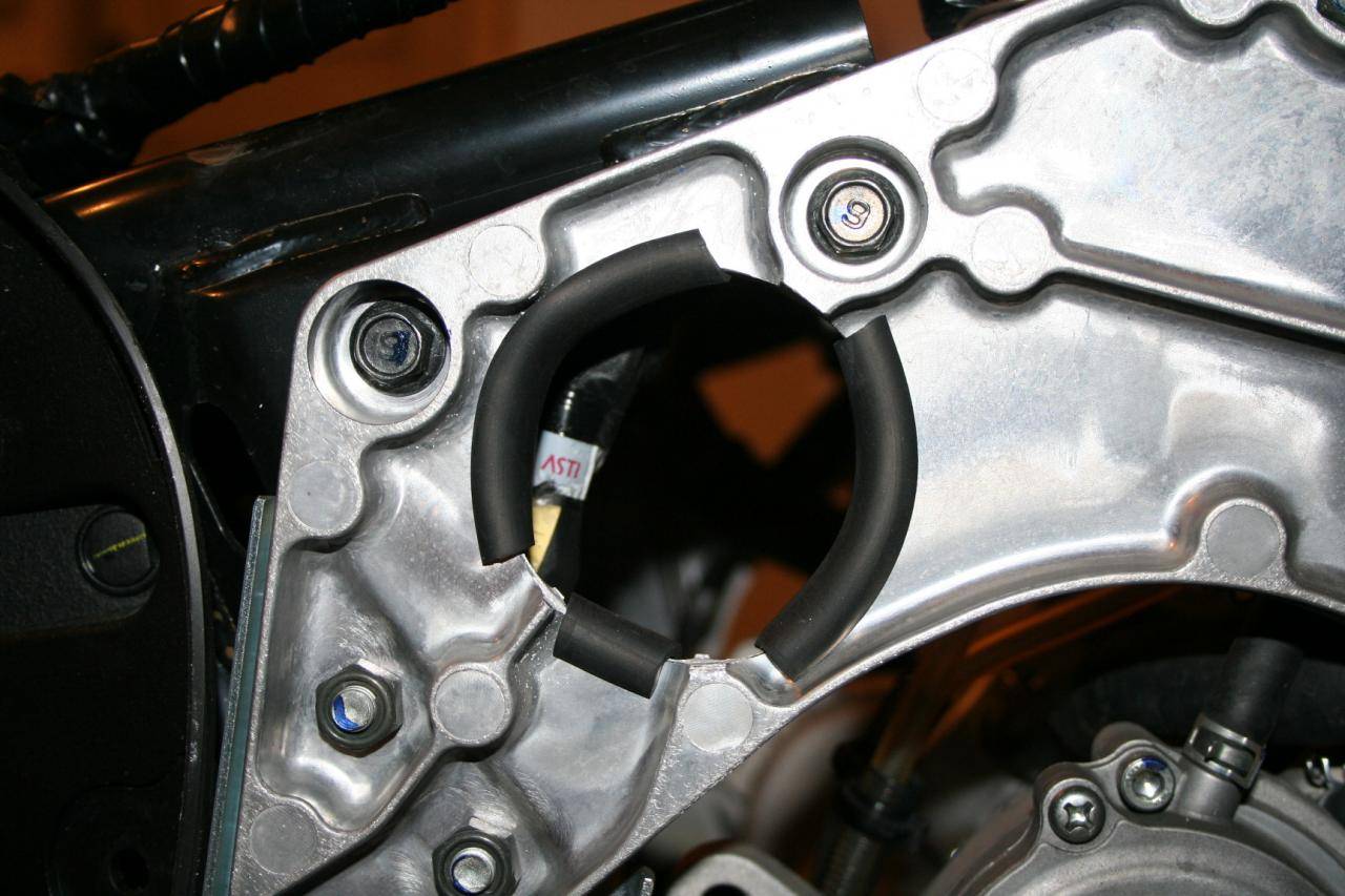
48. Cut 3 small pieces of Rubber Edge Trim to fit the bulkhead.
We recommend gluing them in place with a 3M Gasket & Weather Strip Adhesive Glue or similar.
See Figure 27C.


At this point I realized I had made a mistake.
I installed the rubber insulation on the LH side as well as the RH side.
Looks like that was NOT necessary, so I will probably be removing it from the RH.....


Cut and test fit the 3 strips
picture.php


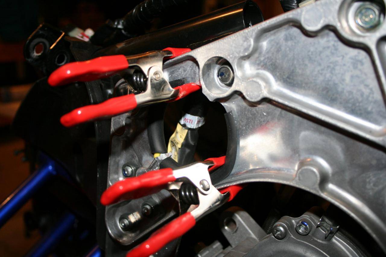
Glued and clamped just like before.
picture.php
 
Last edited:

christopher

Well-known member
Staff member
Lifetime Membership
Nov 1, 2008
81,508
27,371
113
Rigby, Idaho
49. Remove the radiator overflow mounting tab from the black tubular cross-member.
Dress all sharp edges
See Figure 28.


picture.php


picture.php


picture.php


Out comes the grinder and away goes the tab!
picture.php


The tab is GONE.
picture.php
 
Last edited:

christopher

Well-known member
Staff member
Lifetime Membership
Nov 1, 2008
81,508
27,371
113
Rigby, Idaho
50. Install the grey hose (14mm; that went from the air box to the top of the oil tank) onto the oil return barb on the front of the engine just below the billet water manifold.
Use an OEM spring clamp.
See Figure 29.


Ran into a problem here.
I installed the OFT Rollover kit on my Sled.
This valve ended up in exactly the wrong position to be able to reuse the grey hose. So I had to use some regular none formed hose instead.
picture.php


So far it "appears" that standard hose will work OK.
picture.php


I removed and reused the protective sleeve from the original hose.
picture.php
 
Last edited:

christopher

Well-known member
Staff member
Lifetime Membership
Nov 1, 2008
81,508
27,371
113
Rigby, Idaho
51. Install the water thermostat with the 3 hoses still attached.
Use the OEM worm clamp to connect the short hose to the billet water manifold.
Note: the 8.5” ¼ carb heater hose goes all the back next to the case.
See Figure 30.


NOTE:
During my prep I removed ALL of the hoses from the thermostat housing so I could torch off the nipple with greater ease. Now all of them have to be reattached.

picture.php


picture.php


picture.php
 
Last edited:

christopher

Well-known member
Staff member
Lifetime Membership
Nov 1, 2008
81,508
27,371
113
Rigby, Idaho
52. Connect the bottom thermostat hose to the lower heat exchanger outlet with an OEM spring clamp.
Install the supplied #24 (1-½”) rubber coated Adel clamp around the lower thermostat hose and secure it under the upper most M8 chaincase cover bolt.
See Figure 31.


RH side ready to re-attach the lower cooling hose.
picture.php


Hose attaches and fits perfectly once again.
picture.php


But now the hose will be secured to the chaincase cover.
picture.php


picture.php
 
Last edited:

christopher

Well-known member
Staff member
Lifetime Membership
Nov 1, 2008
81,508
27,371
113
Rigby, Idaho
ONE CONCERN I have at this point.

As it stands right now, the thermostat housing is sitting up tight against the RH frame of the sled.
picture.php


This just doesn't seem like a good idea.
picture.php


So I am thinking I may disconnect the short hose between the Thermostat and the manifold the SHORTEN it a bit to relieve some of the pressure that is pushing the thermostat housing into the frame.

Seems to me I could take a Half-Inch or so off of that hose as it just seems too long now.
picture.php


Anyone else that has been down this road have any comments to offer??


Last edited:

christopher

Well-known member
Staff member
Lifetime Membership
Nov 1, 2008
81,508
27,371
113
Rigby, Idaho
If no one is going to offer up a good reason NOT to trim that hose and move the thermostat back away from the frame, then I think I will go ahead and cut it.
 

richracer1

Well-known member
Lifetime Membership
Feb 2, 2011
3,626
2,480
113
Idaho Falls, ID
Obviously I haven't been down that road as far as putting an SC on a sled but been there many times on autos. Your not going to hurt anything by trimming that hose, just trim a little at a time until you get enough clearance to make you feel comfy. Actually, the way it looks from your pic, it needs to be trimmed - notice how it wrinkles.
 
Last edited:
B
Dec 5, 2010
223
142
43
The tab that held on the water tank needs to be trimmed perfectly flush with the cross tube on the subframe. If not, when putting intercooler in it can scratch, or catch a cooling fin and cause damage. Also during riding, motor flex can cause it to rub if not flush with cross tube.I also like to smooth out the support tab on that side that comes down from the shock bolt mount to give just a hair extra space on the backside for the intercooler to slide in and movement of the chassis.
 
T

TRUEBLUEMAX

Well-known member
Aug 4, 2010
751
280
63
Hooper, Utah
Isn't the hole that you drilled on the clutch side for the cold air intake? Just wondering because I don't think all of the kits come with that do they? I just thought if they don't maybe you would want to point that out so that people that don't have the cold air setup wouldn't wonder what you were doing there. Just a thought.
 

christopher

Well-known member
Staff member
Lifetime Membership
Nov 1, 2008
81,508
27,371
113
Rigby, Idaho
The tab that held on the water tank needs to be trimmed perfectly flush with the cross tube on the subframe. If not, when putting intercooler in it can scratch, or catch a cooling fin and cause damage. Also during riding, motor flex can cause it to rub if not flush with cross tube.I also like to smooth out the support tab on that side that comes down from the shock bolt mount to give just a hair extra space on the backside for the intercooler to slide in and movement of the chassis.

Thanks for the insights!
I will go back down and grind that tab 100% of the way GONE.

And grind off a bit of the Shock bolt mount as well.
 

christopher

Well-known member
Staff member
Lifetime Membership
Nov 1, 2008
81,508
27,371
113
Rigby, Idaho
Isn't the hole that you drilled on the clutch side for the cold air intake? Just wondering because I don't think all of the kits come with that do they? I just thought if they don't maybe you would want to point that out so that people that don't have the cold air setup wouldn't wonder what you were doing there. Just a thought.

I know they sell the Cold Air Intake as an option.
But when the State 1 kit arrived that was part of it.
And in the instruction manual it makes no mention of that being an optional step, so I am guessing that it is now included in the kits??
 
T

TRUEBLUEMAX

Well-known member
Aug 4, 2010
751
280
63
Hooper, Utah
I know they sell the Cold Air Intake as an option.
But when the State 1 kit arrived that was part of it.
And in the instruction manual it makes no mention of that being an optional step, so I am guessing that it is now included in the kits??

That is probably a good thing. I know one of the big battles the supers have is underhood heat. It really should be standard on that kit.
 

christopher

Well-known member
Staff member
Lifetime Membership
Nov 1, 2008
81,508
27,371
113
Rigby, Idaho
Went back in and trimmed that hose.

picture.php


Removed about a half an inch of hose.
Fits much better now and isn't pressed up hard against the frame anymore.

picture.php


christopher

Well-known member
Staff member
Lifetime Membership
Nov 1, 2008
81,508
27,371
113
Rigby, Idaho
SUPERCHARGER INSTALL

53.
Slide the supercharger part way into the sled. See Figure 32.

54.
While looking at the inlet to the supercharger rotate the unit
counterclockwise a little. See Figure 33.

55.
Now slide the supercharger further in as you rotate the unit back clockwise. See Figure 34 & 35.

56. Bolt the supercharger into place using two M8x25 flange head bolts (provided) on the top, a M8x35 flange head bolt in the front lower hole and a M8x40 flange head bolt in the rear lower hole (provided & used earlier on the template) on the bottom (note: at the end of the project you will have 2 extra M8x40 bolt left over – used on template). See Figure 36.


picture.php


This is a TIGHT FIT, and you really do have to "Wiggle" it around a bit to get it to drop into place.
picture.php


That electrical harness line had to be moved before the SuperCharger would drop in.
picture.php


First try at getting it through the hole.
And yes, I had to remove all of the rubber insulation that I had previous installed on accident.
picture.php


picture.php


ALL of the hoses fit VERY tightly.
I had to go back in and twist the Hose Clamps to a different position so they wouldn't rub on the other hoses.
picture.php


I also had to move the thermostat house backwards a good inch or so for the supercharger to fit into place. This means I will likely go and trim 2-3 inches off the UPPER heat exchange hose as it is too long now.
picture.php


The Supercharger is in place and the 4 bolts are in.
picture.php


Just to show how far back the thermostat housing had to be moved.
picture.php


The Final Result.
picture.php
 
Premium Features