• Don't miss out on all the fun! Register on our forums to post and have added features! Membership levels include a FREE membership tier.

GEN II, our home built snowbike project

swedenturbo

Well-known member
Lifetime Membership
Dec 4, 2009
330
397
63
Sweden
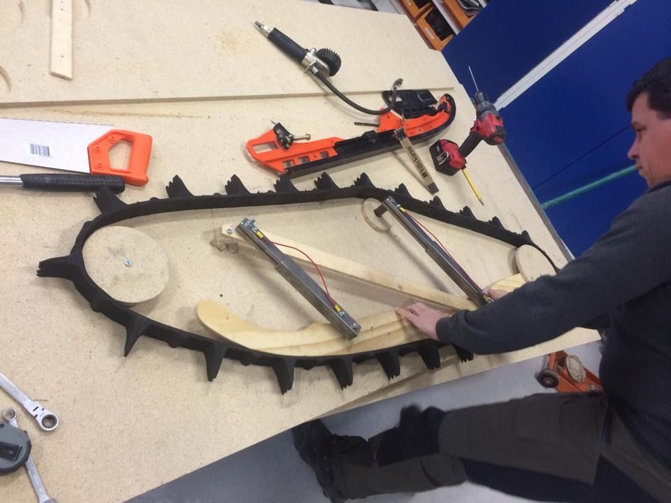
After some testing I've concluded that the scratchers doesn't work.
Must figure out a new solution.

Our final trip to the Swedish Mountains May 9 th
881077d2ef345f9d53b5f98a857f2c0c.jpg

Using our custom made snowbike hauler.
ebuzaqaq.jpg

y5ehyty8.jpg

Filmed using the new Quadrocopter, a DJI Phantom 2 with Zenmuse 3D gimbal. Not the best resolution, something wrong in settings between Gopro and editing app. Must learn more. Will be amazing shots next season!
<EMBED type=application/x-shockwave-flash height=385 width=640 src=http://www.youtube.com/v/P79mesvFFG0>
</EMBED><!-- / message --><!-- edit note -->
 

swedenturbo

Well-known member
Lifetime Membership
Dec 4, 2009
330
397
63
Sweden
We try to find simpler solutions to most of the parts for the construction of our next track kit.
Our goal is to make it quicker and easier to build.

Here is an example:
Our frst ski mount was previously made of a one piece of shaped and welded aluminum, more like a reproduction of Timbersleds.
6ac5dbc970ca25808fa0919a751369a7.jpg


The next refined mount needed no bending or welding.
Just 8 mm aluminum watecut side panels.
a75c2196ca5fd4c29254214f797413b6.jpg

However, the ski spinle required a lot of milling.
8e5dacd473f609f588a616821be17a7b.jpg


95f215c36e9ba44d349027a0e2448d84.jpg

Here is our latest solution where no ski spindle is required. Just some spacers and sleeves.
All parts are water cut of 8 mm aluminum and bolted together.
10669988_852868204747240_2842661547610581391_n_zps5j5oktbz.jpg


10433312_852868234747237_7812621500877880642_n_zpsmbsladti.jpg
 

swedenturbo

Well-known member
Lifetime Membership
Dec 4, 2009
330
397
63
Sweden
We are currenly working on an update to our GEN II build.
The kit works great but as always some small refinements every year.
Here are our thougts so far:
- Move the drive shaft 30 mm forward and 20 mm upwards
- Suspension will be moved the same amount as the drive shaft.
- Changed suspension mounting points
- New shocks with other lengths and stroke.
- New tunnel panels will be required, new design.

We want to lower the ride height as much as possible. Moreover, the rear part of the suspension was previouly slightly too high.

These changes will decrease the ski pressure slightly, enhanced suspension performance and lower ride height.

To know what is required, we have made a simple wooden mockup.
Then we can easily see what happens when design changes are made.
10704159_10152492232362672_7023907599598642017_n_zpsy4gapqfc.jpg


Gen II has a reinforcing rim on the chain case. This solution has worked very well, it makes the kit very strong and rigid.
b6391fa85064bcc9ca8d37b65d910a79.jpg


Manifacturing the rim with bending, machining, drilling and tapping is way too much work. Having a enclosed cover for the chaincase may not be necesary? Motor chain's exposed in the open, right?

Testing out a simpler solution to stiffen the tunnel in a new way that is much easier to manufacture.
This particular prototype will be mounted on our first build as a testbed for future designs. In the picture it's temporary mounted. The idea is that a 8 mm cover spaced with aluminum spacers and bolted in several places should reinforce the structure.
The chaincase cover will be open and just a proection from the chain.
a857cc44f4ca9dae6440b0113915d54b.jpg

c417d2d4958e773d8907c740758763e6.jpg
 

swedenturbo

Well-known member
Lifetime Membership
Dec 4, 2009
330
397
63
Sweden
Have now reposted all earlier posts that had missing photos.
Maybe some administrator can put them in right sequense
 

swedenturbo

Well-known member
Lifetime Membership
Dec 4, 2009
330
397
63
Sweden
Our last ride 4:th to 9:th of may. Expectations were high as this area is one of the nicest in the swedish mountains. Glaciers and steep climbs. Unfortunately the weather went extremely bad. Clowdy, rain and windy. Mostly stranded in our cabin most of the 6 days...

Loaded the bikes on our custom hauler in clear skies but as we reached the cabin, 50 kilometers from the closest road, the weather went bad ;-(
7a6245ee1a50103f52fd299fe897fa5a.jpg

11c4d0ce9b45c49effc69f7eaee082b9.jpg


To summarise the 2015 season is that we made a lot of progress. Our redesigned suspension works a lot better than 2014 edition.
Developing your own snowbike kit is a lot of trial and error. We're learning more each year. GEN 3 is on our drawing board. Maybe we start a new thread as we go. In some aspects, we're trying to think outside the box.
Bought new set of bikes last summer and will be our next testbed for our next build. This time we're running naturaly aspirated. Keeping our turbo bikes as they work really well. Turbo will be our first pick!
64ee333c852e57288427ab591e718271.jpg

Stay tuned....
 

turbolover

Enduring the heat till Braap Season
Staff member
Lifetime Membership
Jul 4, 2001
4,039
3,061
113
Rigby, Idaho
Nice work. Very interesting to see the progress of someone putting this kind of thing into reality.
Keep us updated on the new kit progress and changes.
 

swedenturbo

Well-known member
Lifetime Membership
Dec 4, 2009
330
397
63
Sweden
The 2016 season is gladly on the way! We're into some modifications....


We haven't been completely satisfied that we have'nt had a rear bottoming protection in the rear suspension. The rear shock bottoms 60mm above the rails. In this geometry, the impact bottoming would become big and ugly.
Now, this was originaly calculated and predicted when we made our wodden mockup.
The reason to our geometry was originally that we saw in our wooden model that, if you allow longer suspension travel, the track would hit the tunnel when rear was fully compressed and front fully outsprung.
We have now realized that this is a extreme suspension scenario hardly occurs in practice.


The rear attachment hole will be moved 15mm forwards and 5mm downwards. In that way we will gain 40mm travel and additionally mount a 20mm rubber bottoming impact protection on the rail.
We think this will work even if in this case we will lay down the rear shock slightly and thus makes it softer.
We've previously ridden with a modest 60-70 psi, which means we have posibility increase pressure if it would feel too soft with the new damper angle.
Due to new attachment points in rear, this will require new tunnel panels.
12115944_1070928752941183_1578110400725419694_n_zpsauytg01i.jpg

12079666_1070928772941181_4625265738196790231_n_zpsgfdnohwp.jpg

Cutting out new tunel panels gets the oppurtunity to remove some material. In particular at the right tunel panel, close to the drive shaft. The reason is to get more clearence. Better to hit a stone or stump with the track than to hit it with the tunel panel.
A plastic protection similar to our chaincase cover would make the trick ;-)
11225068_1070929919607733_6286777090336271527_n_zps2uelpowa.jpg

12118990_1070930402941018_7579604807108762594_n_zpsaewvy33y.jpg
 
Last edited:
D
Feb 10, 2014
1
0
1
29
Really nice build.. have you had a chance to test drive the new suspension design? Im looking to upgrade mine to your gen 2.5 for this winter. Do you mind publishing some blueprint of your last design?
 

swedenturbo

Well-known member
Lifetime Membership
Dec 4, 2009
330
397
63
Sweden
Thanks guys!


Sorry for missing pics in this thread. This is all messed up as forum or Tapatalk refuses to show uploaded photos. F
mad.gif
ck!!
Photo links are working but shows as a black X
Don't know why. Nobody seems to give any advise whats wrong....


The kit has worked incredibly well with no big issues.


Continuing with some minor improvements. Our work as an everlasting prototype build that gets improved each year ;-)


The one thing we've seen was some cracks on one of the connecting tubes of the frame.
We think it comes down to the extremely rigid aluminum rim of the chaincase. No flex at all which is great!
This rim distributes forces more firmly to first connecting tube of the tubular frame.
No brace similar to the other connecting tubes can be used due to the path of the chain.
This is no big deal but we want to make it stronger by welding a square tube with some more reinforcements.


Foumlrstaumlrkning%202_zpsyeeocp8w.jpg

Foumlrstaumlrkning%203_zpszw3ohkgq.jpg


We have redesigned our GEN 2.6 tunnel panels.
New rear suspension attatchment holes that will offer more travel. We have also kept previos holes in case we would like to go back to the old suspension geometry.
The red dot shows the new hole.
Sidoplaringtar%2026_zpsyutbbuux.png


In this link you can download the DWG-file for the latest 2.6 tunnel panels.
https://www.dropbox.com/s/0xp4uohsnccmu2i/Sidoplåtar GEN 2,6.dwg?dl=0
 
Last edited:

swedenturbo

Well-known member
Lifetime Membership
Dec 4, 2009
330
397
63
Sweden
Newly developed ski spindle for the season 2016.
More high tech in the form of billet aluminum and carbon fiber!
Made out of water jet cut 5 mm carbon fiber. We chose to delete previous lightening holes in order not to loose strength or rigidity.
sf2_zpsbkgap27o.jpg

sf3_zpsph0nxcrj.jpg

sf1_zpsmocjtclj.jpg
 

J&L Snowhawk

Well-known member
Lifetime Membership
Jan 3, 2008
1,269
288
83
Aberdeen, SD
stores.ebay.com
Very cool. Can u make bottom center section out of carbon like u did multiple alum sections? How spendy is that stuff? How right rigid is it compared to alum sheet. Could you make side plates from it and how much lighter would they be?
 

J&L Snowhawk

Well-known member
Lifetime Membership
Jan 3, 2008
1,269
288
83
Aberdeen, SD
stores.ebay.com
please

could you share the machining program or blue print for your ski spindle? Like your work!

Newly developed ski spindle for the season 2016.
More high tech in the form of billet aluminum and carbon fiber!
Made out of water jet cut 5 mm carbon fiber. We chose to delete previous lightening holes in order not to loose strength or rigidity.
sf2_zpsbkgap27o.jpg

sf3_zpsph0nxcrj.jpg

sf1_zpsmocjtclj.jpg
 

swedenturbo

Well-known member
Lifetime Membership
Dec 4, 2009
330
397
63
Sweden
could you share the machining program or blue print for your ski spindle? Like your work!

Here´s a link to a DWG-file of our new carbon fibre spindle https://www.dropbox.com/s/psz47nxurkx5354/Skidf%C3%A4ste%20Kolfiber.dwg?dl=0


Holes in the 5 mm carbon fibre panels are 12 mm

We didn't want the bolts or the axle to be in contact with the holes of the carbon..
Spacers and sleeves are therefore machined with a 12x4 mm ends on each side that is inserted in the 12 mm holes.
Bolted together with 8 mm bolts with countersunk washers.
Have no drawings of the spacers and sleeves but hope you get the point of what I mean.
face-icon-small-tongue.gif
 

swedenturbo

Well-known member
Lifetime Membership
Dec 4, 2009
330
397
63
Sweden
Updating the bearings on the jackshaft.
This will be our third and final final solution.
Our main focus is on the bearing close to the chaincase of the jackshaft . This bearing will take the load both from the engine and also the load of the chain to the track. Concider the jackchaft as a seesaw with this bearing in the middle.

Our first design was based on dual 6005 bearings.
It turned out that all load ended up on only the first bearing and the second bearing was unloaded.
The next design was a single C3-rated 6305. This was much stronger bearing that should withstand the heavy load.
Have ridden with this setup the whole 2015 season but when we disassembled the kit this fall, we saw that this bearing was more or less completely siezed.

Because of that the 6305 bearing was hugely beefy the conclution to the problem was misallignment.
Single row deep groove ball bearings can't handle large angle changes.
Our movable jackshaft is a great feature to adjust chain tension but requires that the shaft is perfectly aligned in relation to the bearings. This has proved to be impossible to achieve.


The solution is to switch to a double row sealed spherical roller bearings. These allow large angular changes and are considerably stronger.
If you compare with an ordinary 6205 bearing, these new bearings are really much stronger.
These bearings can handle almost 6 times more static load and more than 3 times more dynamic load.


Here are the finished machined housings.
3e5ef342efdf35ce3715dbd5ef11d5f9.jpg


Since they have a hole for lubrication we mounted grease nipples on both housings.
8c5541e4c811186d2120918a160d24fb.jpg

Due to the new bearings, this will require a new brake disc with a newly manufactured hub.
da2fcaf91c451867684f2a703d159046.jpg

c057fa7ec49d63a0a67d4971bae068d1.jpg

cea05970198860791a73d0e776e26eab.jpg

Machined spacer sleeves and test mounted the asembly of the new jackshaft.
793419bafe4bdac36e9431944fab86fd.jpg


Here we see that the spherical bearings can easily handle large misalignment angles without any problems.
cc70078e137d7192f09ad484f1548588.jpg

7781c82be55553b35ecba68f46c6df4a.jpg

d7fceb3f6b2f2dcf9371e66ac63e17d3.jpg

We think this might also be a good update on the bearing housings of the Timbersleds. Although they don't have a movable jackshaft, we all know that flex can damage the bearings.
 
Last edited:

swedenturbo

Well-known member
Lifetime Membership
Dec 4, 2009
330
397
63
Sweden
Finally some progress on our build.
The track kit fitted on the new bike. Lots of work left to do to get it in running order.
3e668958c55423de1566438de0a9458b.jpg

f9c01da7a7dcc20c86e6e86f1fabc75c.jpg


Gonna test a new stere this winter. This stere from RSI will rise 30 mm and will be 60 mm narrower. Have previously ridden with 2" Prox risers. They are bulky and not that fancy. In combination with risers from a KTM Freeride they will have a total rise of approx. the same.
f8049d5d11a1e791991526090cf036df.jpg

a0f464d9879e21928d9d3618aa624043.jpg

84a8d4d5ff3db4c4992d7a1f1380da84.jpg

dd3b851fa688e8ec14b5637307619c6a.jpg

Higher stere will get a more upright position and more rearward center of gravity and less ski pressure. Narrower stere is nice in tight tree terrain but likely less control. Time will tell if this is the right way to go....
New chain tensioner design that never will loose tension.
Previous design relied soley on the friction bond on the tension pullery bolt. With this redesigned solution, a tensioning bolt will take more load without coming loose.
186c4ab13ed049dcd402778cc48fd807.jpg

Milled the tensioning sprocket fork out of a billet aluminum.
0393c2c117d4f65fb4d68f48409fd7f0.jpg

a681db69643fde23eeb2142edc91e000.jpg

2e2767c82167fbba809fa7e23acdad4b.jpg
 
Premium Features