
Does anyone {mountainhorse?} Know how to make one? And will it work on all 05-08 CFI motors?:light::beer;:beer; Have the procedure but no harness
Follow along with the video below to see how to install our site as a web app on your home screen.
Note: This feature may not be available in some browsers.
Have the procedure but no harness
I had trouble finding one and finally paid about $50 to the Pol dealer.
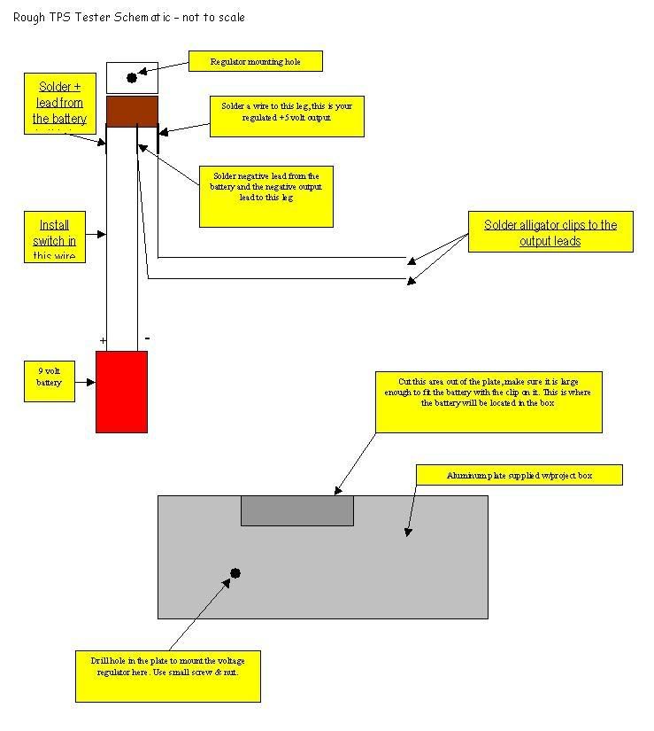
TPS TESTER
These are Radio Shack Parts numbers to assemble a homebuilt Polaris TPS tester.
2761770 - $1.49 +5VDC voltage regulator 1amp
2700324 - $1.99 9 volt battery connectors (they only come in a pkg. of 5)
2701545 - $2.99 Insulated Alligator Clips(come in a pkg. of 6 pairs)
2701802 - $2.29 Project Box
2300875 - $2.69 9 volt Battery
Total price for regulator, 1 battery connector, 1 pair alligator clips,
project box and battery was $7.36.
--------------------------------------------------------------------------------
TPS BASELINE RE--SETTING PROCEDURE
The TPS comes set from the factory and should not need any adjustments. If replacing a TPS or resetting the TPS, Polaris has
developed a TPS test kit for aid in setting the Throttle Position Sensor to specification.
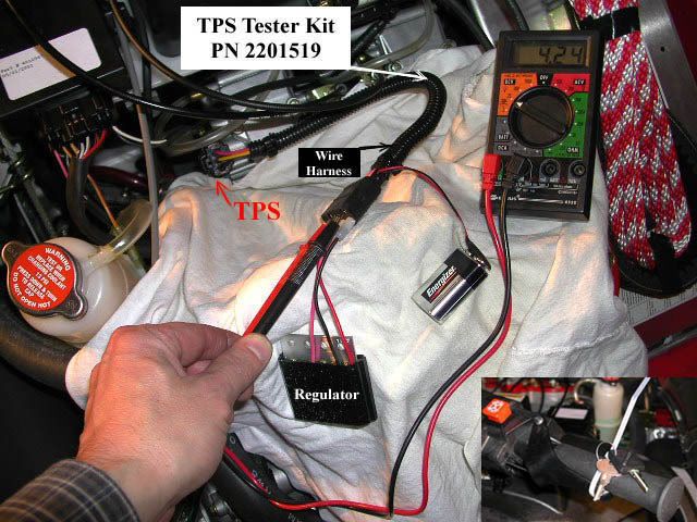
1. Assemble your TPS sensor tool (PN 2201519) as per the instructions that came with the tool.
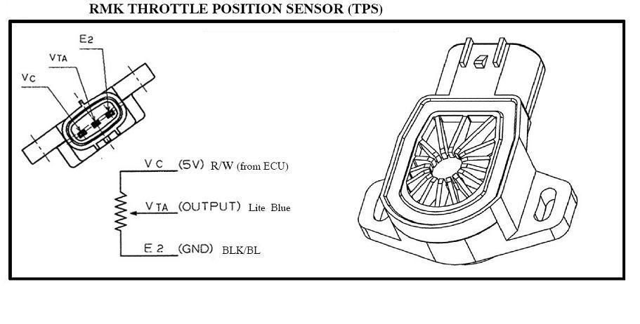
2. Make sure your 9 volt battery is in good condition by inserting the black voltmeter probe from your Fluketmeter in the black
terminal and the red probe into the pink terminal. Voltage should read 4.99 to 5.01 volts. If not, try a new 9 volt battery.
3. Insert the red voltmeter lead into the terminal above the pink wire, and the black meter lead to the terminal above the black
wire. Slowly open throttle and check for smooth voltage change.
NOTE: The Fluke meter will change scales and show O.L. momentarily when throttle is opening.
4. Remove the throttle cable in order to take the slack out of the cable.
5. Back off the idle lock nut counterclockwise and then back out the idle adjuster (A) counterclockwise until the screw tip (B)
separates from the adjusted lever tab.
6. Turn the synchronization screw (C) counterclockwise until the synchronization lever is touching the synchronization screw
hole (D) tab.
7. Remove the connector from the TPS on the throttle body and install TPS sensor tool on to the TPS.
8. Place a shop towel under the throttle body incase you loose grip on the spring or thread a small wire around it if it should fall.
9. Remove the synchronization lever tab spring (E) and gently open and then close the throttle plateswith the throttle, allowing
the plate to close gently. Note the voltage at this point.
10. Insert the synchronization lever tab spring and screw.
11. Turn the synchronization screw clockwise until the volt meter reads the voltage level that you noted in step #8.
12. Loosen screws on the TPS sensor (F).
13. Adjust the TPS sensor until the voltage on the volt meter reads .705 -- .715 volts.
14. Tighten the TPS retaining screws, making sure that the voltage continues to read .705 -- .715 volts.
15. Turn the idle set screw clockwise until the voltage reads .930 volts.
16. Voltage at the yellow terminal should be .920 -- .940 volts at idle. Once the TPS voltage is verified and set, remove the sensor
tool and re--install the TPS harness