• Don't miss out on all the fun! Register on our forums to post and have added features! Membership levels include a FREE membership tier.

Installation and Review: Mountain Performance Inc, Stage 1 & 2 Supercharger

Thread Rating
5.00 star(s)

christopher

Well-known member
Staff member
Lifetime Membership
Nov 1, 2008
81,512
27,372
113
Rigby, Idaho
THROTTLE BODY PREPARATION
57. Zip-tie all vacuum lines and both ends of the larger IAC line. See Figure

picture.php


Every single line has to be Zipped Tied off.
picture.php


picture.php


And more Zip Ties
picture.php


There are a LOT of lines!
picture.php
 

christopher

Well-known member
Staff member
Lifetime Membership
Nov 1, 2008
81,512
27,372
113
Rigby, Idaho
Got cut short on getting this section done today.

Have some business in Boise I have to attend to so won't be able to finish this section till next week.

But I have to say.

It sure looks DAMN SWEET to have to Super Charger sitting in my Nytro now!!
 

christopher

Well-known member
Staff member
Lifetime Membership
Nov 1, 2008
81,512
27,372
113
Rigby, Idaho
Installation and Review: Mountain Performance Inc, Stage 1 Supercharer (Part 4)

58. Remove a rubber plug from each throttle body. These are located next to the grey OEM hose connections.

Each Throttle Body has one of these little caps that has to be removed on it.
picture.php


picture.php
 
Last edited:

christopher

Well-known member
Staff member
Lifetime Membership
Nov 1, 2008
81,512
27,372
113
Rigby, Idaho
59. Install the New Pressure Manifold included with the kit. This is the Manifold with hoses pre-connected to every port. The outlet points toward the LH side of the vehicle. See Figures 37A, 37B, 37C & 37D.

60. Zip Tie all new connections of the Pressure manifold.


As you can see from this image, some of these hoses seem excessively LONG. I did not trim them as I wasn't sure if there was some compelling reason for their length. But if I had it to do over again, unless told otherwise, I think I would trum the hoses to make a tighter fit as everything fits SO TIGHTLY when it all goes back together again.
picture.php
 

christopher

Well-known member
Staff member
Lifetime Membership
Nov 1, 2008
81,512
27,372
113
Rigby, Idaho
61. Remove the black IAC inlet line with woven fabric from the throttle bodies. See Figure 38.

62. Install the new IAC hose supplied in the kit. This routes to the LH side of the vehicle and will be connected to the LH side of the intercooler in a later step.


This is the hose that has to be removed.
picture.php


Once the hose has been removed.
picture.php


The new hose the MPI Supplied.
picture.php
 

christopher

Well-known member
Staff member
Lifetime Membership
Nov 1, 2008
81,512
27,372
113
Rigby, Idaho
63. Remove the 2 M5 screws holding the fuel rail to the throttle bodies. Remove the 2 cylindrical spacers, YOU DO NOT HAVE TO REMOVE THE FUEL RAIL. Install the supplied throttle body adaptor spacers; install but do not completely tighten the 2 fuel rail screws. This allows for better alignment. See Figure 41.


picture.php


picture.php


The bolt comes out.
picture.php


The OEM Cylindrical spacer is removed.
picture.php


And the new MPI Spacer is inserted.
picture.php
 

christopher

Well-known member
Staff member
Lifetime Membership
Nov 1, 2008
81,512
27,372
113
Rigby, Idaho
64. Locate the throttle body adaptor plate. Insure that the small diameter o-rings are pre-installed on the underside of the plate. Install the plate and attached it to the spacer brackets you just installed with 2 M5x10 socket head screws. Use blue Loctite, but do not completely tighten yet. See Figure 42.


picture.php


picture.php


picture.php
 

christopher

Well-known member
Staff member
Lifetime Membership
Nov 1, 2008
81,512
27,372
113
Rigby, Idaho
65. Install the “L” shaped brackets on the front side of the throttle body adaptor plate. Use 2 M5x20 socket head screws. Use blue Loctite. See Figure 42.

66. Tighten the 4 socket head bolts that hold down the throttle body adaptor plate and also tighten the two screws that hold the fuel rail in place.

picture.php


picture.php


More Locktite.
picture.php


The Finished Result.
picture.php
 

christopher

Well-known member
Staff member
Lifetime Membership
Nov 1, 2008
81,512
27,372
113
Rigby, Idaho
67. Thoroughly clean the intake manifolds and the throttle body throats with brake cleaner. Never use any adhesive on the throats of the throttle bodies.

One good shot of brake Clean and the throttle bodies were as good as new.
picture.php
 

christopher

Well-known member
Staff member
Lifetime Membership
Nov 1, 2008
81,512
27,372
113
Rigby, Idaho
67.5 If you are installing a fuel system upgrade (recommended above 6 PSI at sea-level and above 10 PSI at altitudes above 6000 feet), install the regulator onto the fuel rail now.

68. Install the throttle bodies. It is easier to connect the RH carb heater hose (the 8.5in supplied hose with its other end connected to the water manifold) before you seat the throttle bodies. Also reinstall the throttle cable if you removed it from the throttle bodies earlier. Adjust the cable free play per the OEM service manual.

Note: We recommend leaving the cable attached to the throttle bodies and disconnecting from the thumb trigger.


picture.php


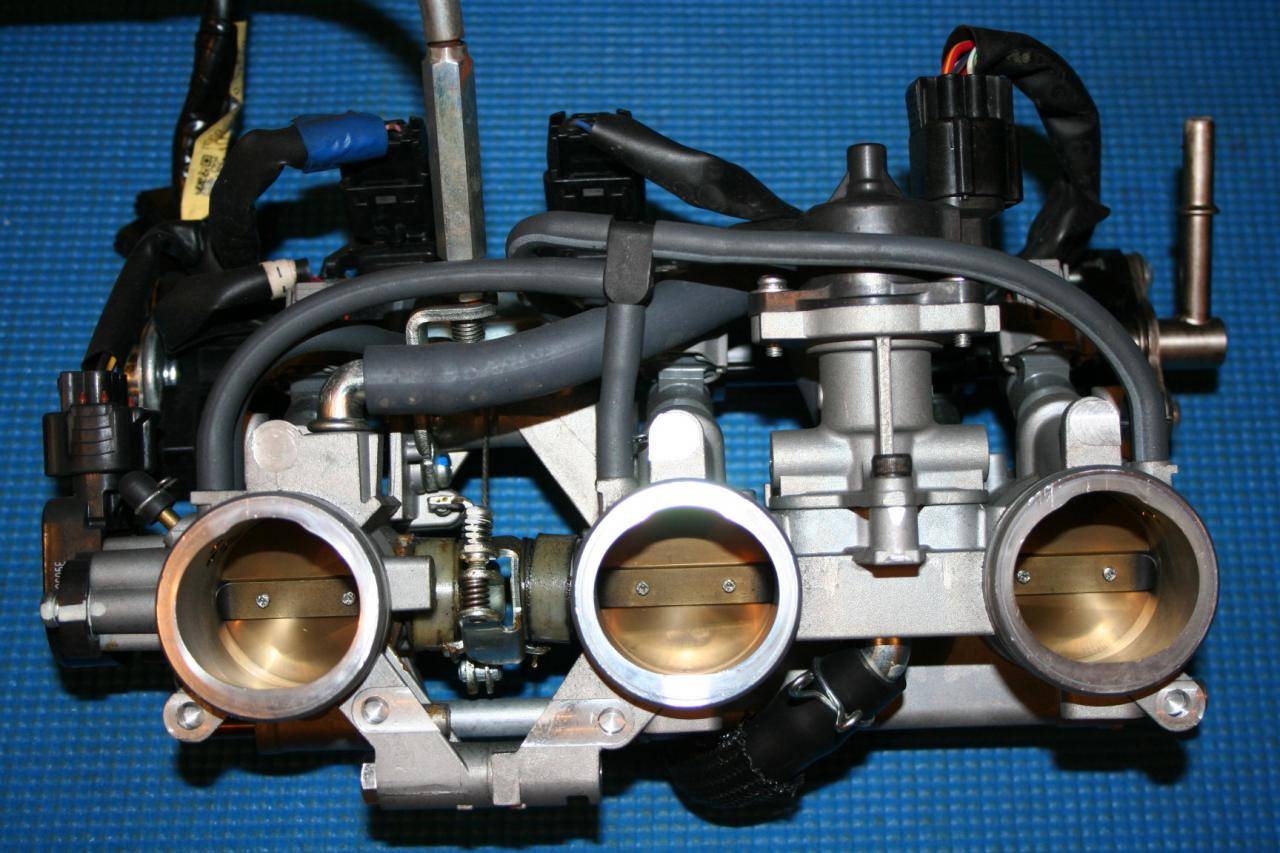
Preparing for the first test fit of the Throttle Bodies.
picture.php


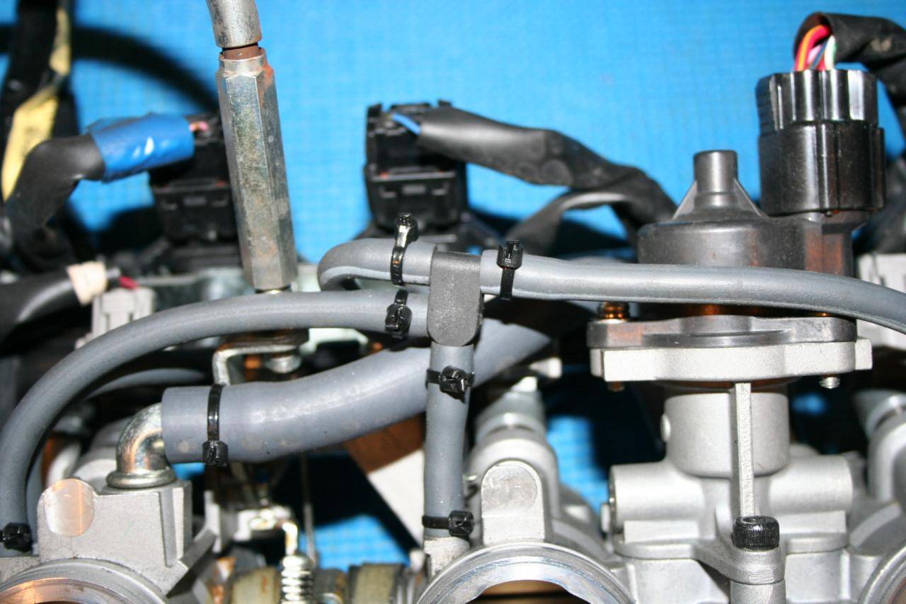
The RH Carb Heater hose.
picture.php


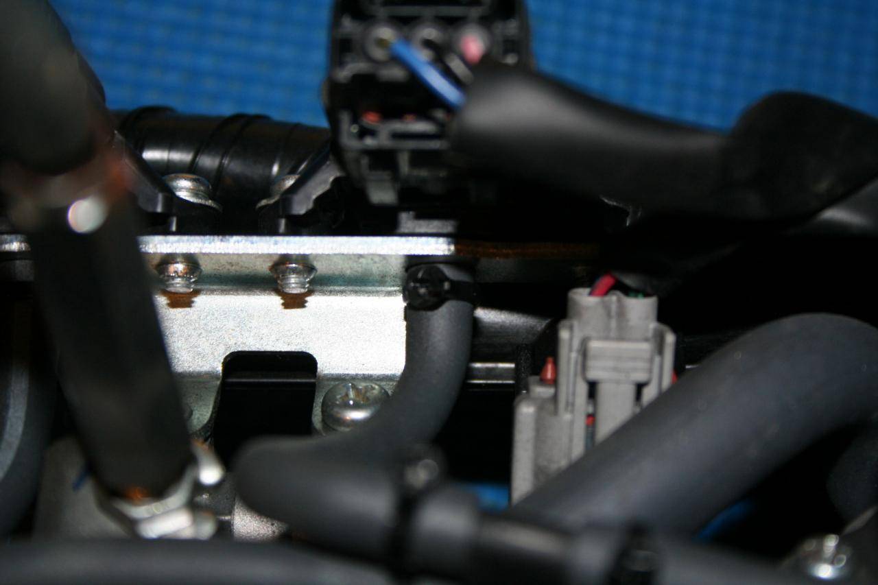
One happily attached RH Carb Heater Hose.
picture.php


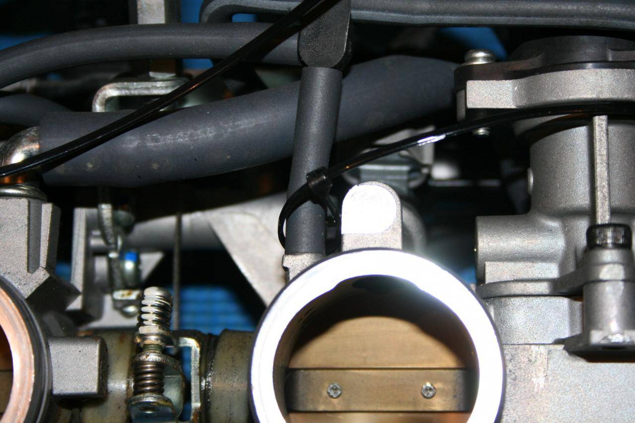
And as I lowered the manifold down into the rubber gaskets, I ran into my first problem. The tolerances on this kit are "TIGHT". The hose clamp was pressing up against the Thermostat sending unit.
picture.php


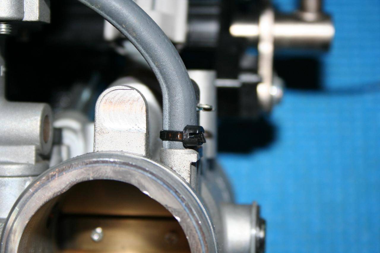
Once the hose clamp was loosened and rotated back more then it allowed the manifold to drop down onto the rubber gaskets smoothly and without any further interference.
picture.php
 

christopher

Well-known member
Staff member
Lifetime Membership
Nov 1, 2008
81,512
27,372
113
Rigby, Idaho
69. Tighten the throttle body to manifold clamps. Install the LH carb heater line. Do NOT remove the OE spacers in the clamps! They tighten fine with the spacers and over tightening will cause problems. See Figure 43.

70. Connect the water sending unit wires to the sending unit. See Figure 44.

picture.php


Back in place using the OEM Clamp.
picture.php


A view from the other side of the engine showing just how TIGHT all of the hoses are now.
picture.php


Reconnecting the Thermostat sending wire.
picture.php


picture.php
\

The Finished Result.
picture.php
 

christopher

Well-known member
Staff member
Lifetime Membership
Nov 1, 2008
81,512
27,372
113
Rigby, Idaho
SUPERCHARGER OIL SYSTEM – 1st Half

71. Use the Oil tank bracket as a template to mark 2 holes in the lower center frame (between the 2 A-arm bolts). You should mount the bracket as high as possible. The marks in the figure are a little low. Use a 3/16 drill and mount the bottom bracket with 2 rivets provided. Note the orientation of the bracket. See Figure 45.

picture.php


picture.php


Holding the bracket in position so I could mark where to drill.
picture.php


Have center punch will travel.
picture.php


Drilled it as HIGH and close to the curve as I could
picture.php


picture.php


Set the Rivet and the lower bracket is mounted.
picture.php
 

christopher

Well-known member
Staff member
Lifetime Membership
Nov 1, 2008
81,512
27,372
113
Rigby, Idaho
72. Again, using an oil tank bracket as a template mark the lower bracket hole in the top tubular cross member. Install 1 rivet. Now, bend the bracket’s mounting tab around the cross member and install a second rivet in the top hole. See Figure 46.


Test fitting the canister so I could position the upper bracket.
picture.php


picture.php
 

christopher

Well-known member
Staff member
Lifetime Membership
Nov 1, 2008
81,512
27,372
113
Rigby, Idaho
73. Install the oil tank as shown. Note the orientation of the top return fitting (about 2 o’clock as you face the front of the sled). See Figure 47.

picture.php


picture.php
 

christopher

Well-known member
Staff member
Lifetime Membership
Nov 1, 2008
81,512
27,372
113
Rigby, Idaho
74. Route the small oil tank vent line over the top of the Yamaha ECU and secure it with 2 zip-ties. THE PLACEMENT OF THIS OIL LINE IS CRITICAL.

THE END OF THE HOSE NEEDS TO BE LOWER THAN THE OIL TANK ITSELF TO PRESERVE OIL INCASE THE VEHICLE IS FLIPPED OVER.

ADDITIONALLY AND EVEN MORE IMPORTANTLY, THE END OF THE VENT LINE CAN NEVER SIT IN SNOW OR ICE.

IF IT WERE ALLOWED TO IT COULD SUCK WATER INTO THE OIL WHICH WILL CAUSE
UNWARRANTABLE AND PERMANENT DAMAGE TO THE SUPERCHARGER.

See Figure 48.

picture.php


picture.php
 

christopher

Well-known member
Staff member
Lifetime Membership
Nov 1, 2008
81,512
27,372
113
Rigby, Idaho
Its coming along.
At this rate I think I will have it wrapped up in September if I don't run into any other major delays.
 
A

acutah

Well-known member
Nov 27, 2007
646
289
63
Kaysville, UT
IF IT WERE ALLOWED TO IT COULD SUCK WATER INTO THE OIL WHICH WILL CAUSE[/U] UNWARRANTABLE AND PERMANENT DAMAGE TO THE SUPERCHARGER.


Been there done that. When the oil cools your vent line becomes a nice little vacuum. Slurp slurp...water in the blower oil means the dumb end of a tow rope and big bucks.
 
Premium Features