We have trough the years, designed built a few different snowbike kits.
A really fun hobby project. Most of all, they are awsome to ride!
We have no plans for serial production. These are only one off prototype builds.
For each year, we learn something new. This is an everlasting product development and test new solutions. It also brings riding your own snowbike to a new level as you always try to improve handling and performance.
Here is a link to our previous project build thread: (sorry that thread is messed up with missing photos, Look at later posts as pics are reposted)
http://snowest.com/forum/showthread.php?t=359272&referrerid=82502


Our GEN 2 snowbike has come to the end of its development and we are excited to begin our next build.
In some aspects, we're trying to think outside the box with some new features.
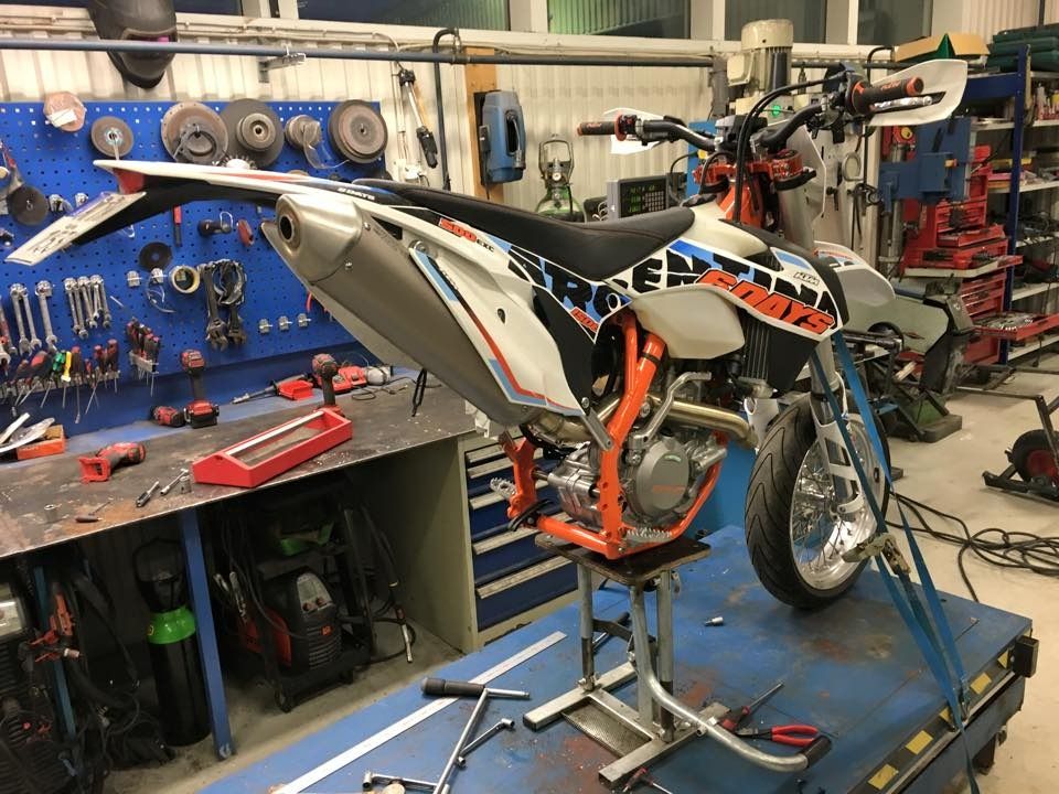
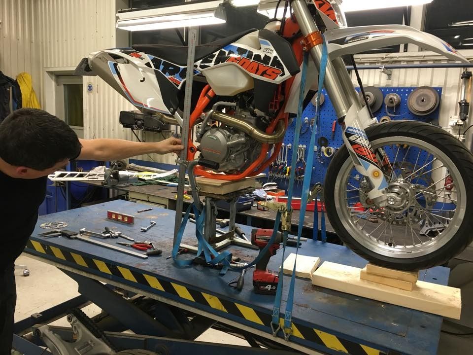
We will keep our dedicated Gen2 turbo snowbikes. This build will be on our normaly wheel equipped "summer bikes", 2015 KTM 500.
We haven't come that far on the project yeat. No machining of actual parts but more focus is on design and make accurate drawings.
We hope to have it ready for testing in early/mid March.
Starting the build thread here and post you some photos and thougts and ideas as we go.
Hope this will inspire more people to build their own custom snow bike

Finally start start of the build!
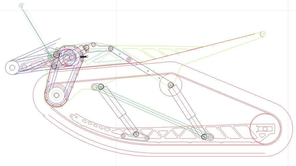
The plan for the GEN 3 is a skid suspension similar to our previous build, the GEN 2.6. It will also have a sprung strut similar to the TSS.
It will not have a welded tubular frame but instead an assembly out of cut aluminum parts that are bolted together. The jackshaft will be moved forward slightly to provide a more compact design and less weight. The track will be a 121" Yeti Maxtrack.
The engine will this time be naturally aspirated but with a Thumper Racing 590 big bore. Why no turbo?
We are really pleased with the performance of the turbo but it's a lot of work to start building a turbo kit all over again. Maybe later, but we are eager to get this kit on snow this winter. BigBore is an easy install even if it doesn't even come close to the performance of a turbo.
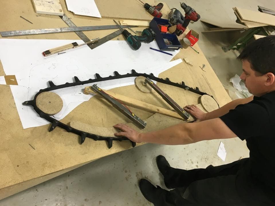
As previous builds, we begin with development of the suspension geometry. An analog mockup has proven to be a necessity at such advanced simulations such as these
.
We have seen that its crutial to get all of the attachment points in the right position to get maximum travel and keeping track tension.
Just by moving one point a fraction of an inch will completley ruin the suspention travel or mess up the track tension.
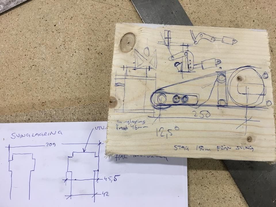
From the mockup, we have come to the conclusion that we will run the same shock length front and rear 360 mm. The travel of the rear suspension is about 250 mm. Suspension strut will give an angle change on the tunnel section with a maximum of approx. 12.5 degrees, which provides an additional travel of approximately 150 mm.
Previous build had to have a sliding rear attachment point on the rail in order to keep the right track tension. By going with a shorter track, we have seen that we hopefully can go for a direct attachment with no sliding part. That simplifies the design and assembly.
The next step is to start making some drawings and produce a few more testmockups, mainly frame and linkage to make sure that everything will fit as planned before we take the next step.
We set the bike on makeshift supports to get the correct ride height. In that way we can take accurate measurements and angles.
Some simple sketches to ponder on before we get on ....
One feature we will test is a suspension strut similar to the TSS. We are not sure that a pivoting kit is good in all conditions. In powder we think that a non pivoting will perform better. On a bumpy trail, additional travel is preferred.
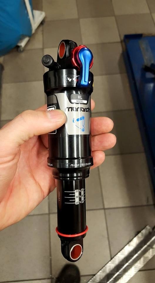
The idea is to use a shock from a mtb bike with the function to lock it in two steps. In this way, we believe we have the best of both worlds: the soft and pliable sprung strut on trail and the best powder snow properties with rigid strut. The locking of the shock will be done by a wire operated lever on the handlebars so you can do it while riding.
You might think that this shock will be way too weak for this aplication but our idea is to use a lever. The lever ratio will limit travel but also reduce load on the shock. By being able to adjust the shocks attachment on the lever we can roughly adjust the hardness and then refine it with air pressure. The lever will have adjustable rubber endpoints in order not to put too much positive or negative load on the shock.
We are really excited to try this!
Parts starts to arrive for the new build.
6-tooth 2.86 "drive wheels from Timbersled. The wheel in the background is 7-tooth that we run on our previous build.
Smaller driver wheels has both advantages and disadvantages.
They make more roll resistance as the track is forced around a tighter radius. Fewer teeth engaged with a higher risk of slipping.
Why we choose to test the smaller wheel is to maintain, or possibly even lift the drive shaft despite a track with higher lugs. The whole package is compact and there is limited space. Higher axle gives at the same time a steeper approach angle , which to some extent reduces deep snow performance but at the same time higher ground clearance. We believe that this overrides the disadvantages that smaller wheel does.

130 mm brake disc is smaller than previous.
The location of the brake disk on the jackshaft is the limiting factor in how much the suspension movement can be allowed of the tunnel until the brake disc hits the plastic parts on the rear of the motorcycle.
For that reason, we will mount the brake on the drive shaft instead, a more neater solution and safer in the case of chain failure.
We will in any case be forced to cut the lower part of the "airbox" in order to get any travel.

Mino caliper to a rear brake of a KTM SX 85 cc. Should match well with the bike's OEM brake main brake cylinder. Earlier caliper had too large volume and we have been forced to switch to a larger cylinder in order to get it to work.
The track is a Maxtrack from Yeti. Looking good!

Stay tuned.....

A really fun hobby project. Most of all, they are awsome to ride!
We have no plans for serial production. These are only one off prototype builds.
For each year, we learn something new. This is an everlasting product development and test new solutions. It also brings riding your own snowbike to a new level as you always try to improve handling and performance.
Here is a link to our previous project build thread: (sorry that thread is messed up with missing photos, Look at later posts as pics are reposted)
http://snowest.com/forum/showthread.php?t=359272&referrerid=82502
Our GEN 2 snowbike has come to the end of its development and we are excited to begin our next build.
In some aspects, we're trying to think outside the box with some new features.
We will keep our dedicated Gen2 turbo snowbikes. This build will be on our normaly wheel equipped "summer bikes", 2015 KTM 500.
We haven't come that far on the project yeat. No machining of actual parts but more focus is on design and make accurate drawings.
We hope to have it ready for testing in early/mid March.
Starting the build thread here and post you some photos and thougts and ideas as we go.
Hope this will inspire more people to build their own custom snow bike
Finally start start of the build!
The plan for the GEN 3 is a skid suspension similar to our previous build, the GEN 2.6. It will also have a sprung strut similar to the TSS.
It will not have a welded tubular frame but instead an assembly out of cut aluminum parts that are bolted together. The jackshaft will be moved forward slightly to provide a more compact design and less weight. The track will be a 121" Yeti Maxtrack.
The engine will this time be naturally aspirated but with a Thumper Racing 590 big bore. Why no turbo?
We are really pleased with the performance of the turbo but it's a lot of work to start building a turbo kit all over again. Maybe later, but we are eager to get this kit on snow this winter. BigBore is an easy install even if it doesn't even come close to the performance of a turbo.
As previous builds, we begin with development of the suspension geometry. An analog mockup has proven to be a necessity at such advanced simulations such as these
We have seen that its crutial to get all of the attachment points in the right position to get maximum travel and keeping track tension.
Just by moving one point a fraction of an inch will completley ruin the suspention travel or mess up the track tension.
From the mockup, we have come to the conclusion that we will run the same shock length front and rear 360 mm. The travel of the rear suspension is about 250 mm. Suspension strut will give an angle change on the tunnel section with a maximum of approx. 12.5 degrees, which provides an additional travel of approximately 150 mm.
Previous build had to have a sliding rear attachment point on the rail in order to keep the right track tension. By going with a shorter track, we have seen that we hopefully can go for a direct attachment with no sliding part. That simplifies the design and assembly.
The next step is to start making some drawings and produce a few more testmockups, mainly frame and linkage to make sure that everything will fit as planned before we take the next step.
We set the bike on makeshift supports to get the correct ride height. In that way we can take accurate measurements and angles.
Some simple sketches to ponder on before we get on ....
One feature we will test is a suspension strut similar to the TSS. We are not sure that a pivoting kit is good in all conditions. In powder we think that a non pivoting will perform better. On a bumpy trail, additional travel is preferred.
The idea is to use a shock from a mtb bike with the function to lock it in two steps. In this way, we believe we have the best of both worlds: the soft and pliable sprung strut on trail and the best powder snow properties with rigid strut. The locking of the shock will be done by a wire operated lever on the handlebars so you can do it while riding.
You might think that this shock will be way too weak for this aplication but our idea is to use a lever. The lever ratio will limit travel but also reduce load on the shock. By being able to adjust the shocks attachment on the lever we can roughly adjust the hardness and then refine it with air pressure. The lever will have adjustable rubber endpoints in order not to put too much positive or negative load on the shock.
We are really excited to try this!
Parts starts to arrive for the new build.
6-tooth 2.86 "drive wheels from Timbersled. The wheel in the background is 7-tooth that we run on our previous build.
Smaller driver wheels has both advantages and disadvantages.
They make more roll resistance as the track is forced around a tighter radius. Fewer teeth engaged with a higher risk of slipping.
Why we choose to test the smaller wheel is to maintain, or possibly even lift the drive shaft despite a track with higher lugs. The whole package is compact and there is limited space. Higher axle gives at the same time a steeper approach angle , which to some extent reduces deep snow performance but at the same time higher ground clearance. We believe that this overrides the disadvantages that smaller wheel does.

130 mm brake disc is smaller than previous.
The location of the brake disk on the jackshaft is the limiting factor in how much the suspension movement can be allowed of the tunnel until the brake disc hits the plastic parts on the rear of the motorcycle.
For that reason, we will mount the brake on the drive shaft instead, a more neater solution and safer in the case of chain failure.
We will in any case be forced to cut the lower part of the "airbox" in order to get any travel.

Mino caliper to a rear brake of a KTM SX 85 cc. Should match well with the bike's OEM brake main brake cylinder. Earlier caliper had too large volume and we have been forced to switch to a larger cylinder in order to get it to work.
The track is a Maxtrack from Yeti. Looking good!

Stay tuned.....
Last edited: