• Don't miss out on all the fun! Register on our forums to post and have added features! Membership levels include a FREE membership tier.

141 Pro RMK

Bushwacker1

Well-known member
Lifetime Membership
Nov 27, 2008
297
183
43
Wisconsin
This project started with ideas that came from a couple swap meets and the bounty I returned home with. The engine was never intended to be for this sled but when I purchased this sled the original plan for this engine was changed. I purchased a 2013 800 Pro Rmk and thought about converting this to a true entry level lower Hp Pro Rmk that will actually be less than 400 Lbs. The 800 was drained of gas and it weighed in @ 440.6 Lbs with the oil tank half full. Other considerations for this sled are the non stock front bumper, a home made steel tube for the rear bumper, and upgraded walker evans clicker front shocks. This was a ways from the dry weight I remember being 416 pounds even when considering the oil and water weight.
picture.php


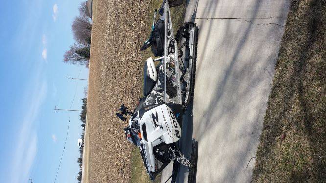
After the new custom single cylinder engine, the shortened skid, a new aluminum rear bumper tube, lower handlebars, and hand gaurds were installed, and the oil tank was filled my first finished weight came in at 369.3 pounds. This was with no fuel and the gauge and wiring was also still not installed. A reduction of 71 pounds. I am also planning on shortening the tunnel so that may also take off some additional weight.
picture.php

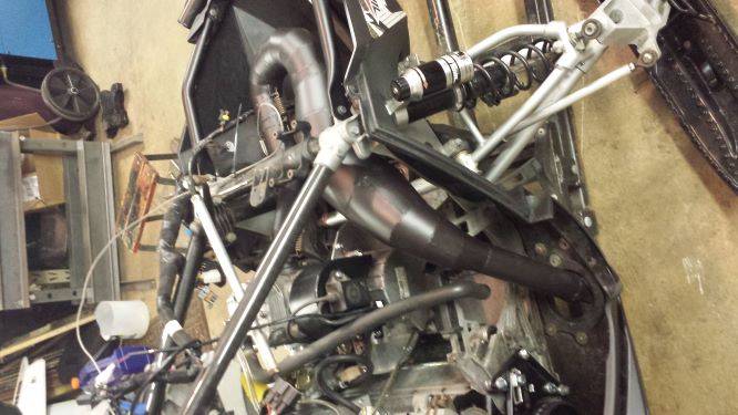
I was able to get this on the snow out west a few weeks ago and started tuning for the pipe and clutching but had some set backs that did not allow me to finish, so I can not yet say this project is a success. I have also realized that my tuning skills are no where near where I would like them to be as this has turned out to be more of a clean sheet of paper that needs to be colored in by the tuner, and although I have a complete box of crayons, sometimes picking the right color is not as easy as one would think it is. I am currently working thru some rework on those issues and will share those in future posts. Some of the rework may affect the ultimate finish weight also. I will be sharing the engine project first and then the engine install.
 
Last edited:

Bushwacker1

Well-known member
Lifetime Membership
Nov 27, 2008
297
183
43
Wisconsin
picture.php

This was what I came home with from a swap meet. I purchased it as spare parts for my sons 1991 Indy Starlite. 250cc air cooled this engine was installed in sleds without an expansion chamber, a 30mm carb, and only a muffler, so that limited the power output. This basic engine also shares parts with the Polaris ATV. I found some info where someone replaced the cylinder with an indy trail fan cooled cylinder. Did some more research and found that the bore and stroke were the same, and the indy trail had much larger ports and ran a larger carb. Some modifications to the cooling fins would be needed to wrap the starlites tin around it but that would have been a good upgrade. If a tuned pipe were made the upgrade would be even better.
picture.php

Went to Hay Days last fall and found a used Fuji Indy 500 cylinder and head. Was able to get it for 10 bucks, and when I got it home I found that the bore and stroke were also the same and the bolt pattern on the base were the same except that one hole would need to be drilled as the Fuji uses one common stud between the two cylinders on the carb side. I took the band saw and cut it in half. It bolted up and the piston and ports all were where they should be. The 500 has the water pump bolted on to the cylinder so I used the mag side and thought it should not be too hard to get that water pump to spin so I prepped the cylinder for welding up the water jacket. The 500 puts out around 80 hp so I am hoping to get around 40 with an expansion chamber and a larger carb. The 250 four wheelers when modified were also in this power range. As this is HP in the same range as a 340 my plan was to gear this sled down for a top speed of around 50 Mph so it will be able to spin a 141 cobra 1.6" lug track.
picture.php

Cut the cylinder head in half and prepped that for welding up the water jacket.
picture.php

Cylinder head welded
picture.php

Cylinder welded
picture.php
 
Last edited:

Bushwacker1

Well-known member
Lifetime Membership
Nov 27, 2008
297
183
43
Wisconsin
Bolted the water pump on and found that the pulleys did not line up. The flywheel position is different between the starlite engine and the 500 twin. The bottom pulley bolt pattern was the same but the locating bore did not fit the flywheel either.

picture.php


Decided to make up a spacer and coolant extension to offset the water pump.

picture.php


picture.php


Made up a spacer to support the water pump.

picture.php


Ordered up some longer bolts from Mcmaster Carr and installed the water pump.

picture.php


Made up an adapter for the bottom pulley that positioned the pulley in line with the top pulley and also centered it on the flywheel so it runs true.

picture.php


picture.php


Installed water pump and pulleys. All lined up now.

picture.php


I installed the belt and found it to be very tight with next to no adjustment. It just seemed to short. Did some measuring and found that the starlite engine has the crank positioned lower in the cases than the twin 500, yet the bore and stroke are the same and the piston is coming to full top dead center as it should. Did some more checking and found that the starlite engine has a longer rod than the 500 twin. With all the issues with the newer 800 engines, and the after market talking about the advantages of a longer rod in those engines, I will consider this a plus for this engine, and hope it provides some of the benefit of improved rod angle. Went to my local parts store and sourced a belt that was a little bit longer.

Started lay out for an adapter to mount a recoil. The fan cooled one did not have enough clearance for the water pump and belt, and would need to cut up to make it work. Then a belt cover would need to be attached. I was going to use the 500 twin recoil but found that due to the longer rod, the top pulley on the water pump would hit on the top of the recoil cover. A spacer would also be needed as the 500 recoil was too shallow. I found that a Polaris ultra recoil had the correct depth with a 500 twin cup installed on the flywheel, but would require a cut out for the belt pathway. I considered using a recoil and belt cover from an indy storm as the recoil has bosses on it for the cover, but found them to be very hard to source, and was unsure if it would have the needed offset depth. I also looked at 650/ RXL recoils and covers but offset was incorrect, and mounting the belt cover would also require me to provide brackets to mount it. I also wanted to mount the ignition coil on the belt cover, so I decided that I would make my own belt cover and the mounts needed to support it. Another thing I found was that the bolt pattern on the starlite engine for the adapter plate was not even close to being designed on a bolt circle pattern. It would have been much easier if Polaris would have just used a bolt circle off the crank centerline but I found no such thing even close to a bolt circle that lined up with anything.

picture.php


Ultra recoil with needed depth to attach to adapter plate.

picture.php


Modified Ultra recoil installed.

picture.php


Made up some mounts that will support the new belt cover and attached them to the adapter plate. These proved to be under designed in the end as vibration cracked my adapter plate and halted my tuning when I was out west. A thicker adapter plate, a different recoil, and belt cover is currently in process of being retrofitted. More to come on that in future posts.

picture.php


Fabricating the first belt cover.

picture.php


Completed belt cover ready for paint. Note the 500 recoil on the floor. (I cut the top off and considered having it welded back on to get the clearance needed for the top water pump pulley.)

picture.php
 
Last edited:

Bushwacker1

Well-known member
Lifetime Membership
Nov 27, 2008
297
183
43
Wisconsin
picture.php


Put the oil line on and found it will not clear the crank case when the cylinder is installed. As I will be using a carb with an oil line on it this hole was plugged so the cylinder could be installed. I found a set of rack carbs that were used on 2001 to 2006 indy 500 Fuji engines. These are 38 mm the same as the round slides that these engines came with up till 2001. I wanted to use a flat slide to improve the bottom end performance and finding a carb that is calibrated to the engine this cylinder came from seemed to be good starting point. This carb uses a different carb boot. I purchased one and found that the bolt span was changed and would not fit. Found that there are three bolt spans used on the Fuji 500 engines. One for the round slides, one for the fuel injected sleds, and one for the flat slide carbs. More research and I was able to find a carb boot for a Ski doo Boysen Rad valve that fits this carb. Made up an aluminum spigot adapter to fit the boot and the bolt span on my cylinder. The carb rack was separated and the fuel port needed to be drilled and tapped on the right side. The left side was tapped and plugged and a hose barb with threads was made for the right side. These rack carbs also came with a two into one choke cable. I was able to pull it apart and eliminate one of the cables. Throttle cable also presented a problem as the round slide cable would not work with the rack style carb. I had one from a 600 edge that fit the carb but the oil pump cable was too long when attached to the oil pump. I ended up taking apart three different assemblies to build one that had all the correct cables and length. Had to use an old style round transition type for the reassemble as the newest type (flat cable to cable transition box) are impossible to take apart and reuse. Still would like to find one off the shelf that fits in case this one breaks.

picture.php


Pulled out the 800 engine. This weighed 95.1 lbs with the exhaust manifold.

picture.php


250 cc engine weighed 48.5 Lbs as shown.

picture.php


Started on motor mounts. I wanted to use the stock mounts. Wanted to move the mag side ones inboard but there was not much room due to the narrow engine. Also the mounts could not be relocated without making some type of adapter to deal with the bulk head differences where they would be relocated to. Found that an under slung type would allow them to be used in the stock position and still be able to mount the engine low in the bulk head. I thought a simple drop arm would work well, just make up two equal length drops and weld to the cross tube. After some measuring I found that none of the mounts are located at the same elevation from the bottom of the bulkhead and the location front to back do not match either. This required the drop brackets to all be different lengths and the cross tubes had to be indexed for alignment before welding them to keep things straight and level. The angle brackets will be used to attach a flat motor plate. There will also need to be some spacers to get the plate to reach the bottom of the engine.

picture.php


picture.php


Engine plate. To keep the engine as low as possible notches were cut in the plate. Engine needs to be pushed outboard to get clutches to line up. Removed a small amount of material from the side of the bulkhead to be sure the motor plate does not rub.

picture.php


Engine installed. Thanks to TRS for info on clutch alignment. I used his and Patricks info from that thread to get my engine lined up. Polaris alignment tool was no where close and if I had went with that as my final word I would have needed to raise the engine a few more inches to get the drive clutch outboard enough.

picture.php


This picture also shows the TKI belt drive installed. I had one for a Pro but the gear ratio was to tall. I spoke to Tom at TKI and he was able to send me a larger bottom sprocket and a smaller top sprocket. 66/ 24. This gives me a 2.75 ratio. After my testing I believe that I may need to get this ratio closer to 3.0 to 1. Did some calculations on this and my current top speed with 8 tooth drivers will be around 66 MPH if my engine runs at 8000 rpm. Changing to 7 tooth drivers will get this down to 58 MPH. I still do not know where this engine will make its power but it should be between 7800 and 8000. I was hoping for a top speed around 50 MPH. I spoke to Tom again but we are out of off the shelf items from him. I am currently working on the possibility of getting some custom sprockets made to improve my gearing closer to 3 to 1.

picture.php


This picture shows the custom air box with a tempa flow installed. (tempa flow not installed yet) I was very happy how it turned out and was able to find some flexible 4" hose and a downspout fitting that plumbed it to the hood plenum. While testing I found that the air box noise was so loud I could not hear the exhaust pipe. This will be another follow up item to try to install a stock air box from a Pro Ride Indy 550
 
Last edited:

Bushwacker1

Well-known member
Lifetime Membership
Nov 27, 2008
297
183
43
Wisconsin
picture.php


picture.php


Here are a few pictures of the air box with the tempa flow installed. Also made up a bracket for the fuel pump and installed. On the first test ride the sled seemed to be running out of fuel. With the fuel pump mounted here I believe the impulse line was too long at around 12 inches. I shortened it up an inch or so and rerouted the fuel line so it would gravity feed to the pump. The issue seemed to go away during the rest of my testing. Reading the Aaen carb tuning book it talks about this problem and he notes that 12" is where problems may surface. Relocating the fuel pump to shorten the line is also on my follow up list of things to do.

picture.php


Another picture of the belt drive installed.

picture.php


picture.php


Custom built pipe. I took the sled to Aaen performance and they were able to build a custom pipe for this engine from one of his blanks. Not sure what the original application was but he said this should run around 7800 to 8000 Rpm in the 40 Hp range. He has offered pipes for this bore and stroke for the 250 cc four wheelers with these results. Olav was most helpful to this project as I would have not been able to get this done in the few days they had the sled. when I first installed the engine I was worried when I saw that the exhaust port was directly in line with the steering post but they were able to offset around it. There are over 20 welds in the fitment of this pipe and it turned out great. This pipe has an internal stinger that acts as a silencer so a large external can was not required. The sled sounds like a dirt bike. It is a little louder than I am used too compared to a stock sled, and we may need to increase the size of that silencer if it turns out to be too loud. I will say that with the open style air box the intake noise was so loud that I could not hear the exhaust after it built Rpm so once I get the air box noise addressed I will need to make a decision on if the pipe needs to be quitter. I also made a plate for the exit port that seals the pipe to the rubber grommet so snow will not back up into the belly pan.
 
B
Feb 6, 2012
79
56
18
48
Nice project, I like more the project light projet than the project which consists to increase the power and the weight.


Complex engine construction! with very affordable parts. I would like to know the weight of the engine finished with the exhaust and the radiator.
 

Bushwacker1

Well-known member
Lifetime Membership
Nov 27, 2008
297
183
43
Wisconsin
The pipe was made in two pieces to be able to install and remove. The first section before it starts to expand out is still on the sled but I would guess it is around one or two pounds. The other section, or the main pipe is off the sled right now so I was able to weigh it and it weighs 6 pounds, so around 8 pounds for the pipe. The cooling heat exchangers are part of the tunnel assembly so there is not a way to weigh them. When I drained the system to remove the 800 engine I captured around a gallon of antifreeze and when I filled the new system it used almost all of that gallon. There may have been a small amount left in the heat exchangers but I would estimate this system holds just over a gallon. The engine was 48.5 lbs as shown in the picture above but the clutch spring and weights or the carb were not included in that weight. There is probably another 2 or 3 pounds added for the coolant hoses, thermostat/ bypass assembly, and coolant bottle.
 
Last edited:
B
Feb 6, 2012
79
56
18
48
Thanks!
So it's very close to the weight of my 4-stroke fan cooled 460cc engines. And the power too (after a lot of changes in my case)

A 2-stroke 1 cylinder liquid cold engine suitable for CVT transmission is very rare.


Last edited:

Bushwacker1

Well-known member
Lifetime Membership
Nov 27, 2008
297
183
43
Wisconsin
Thanks!
A 2-stroke 1 cylinder liquid cold engine suitable for CVT transmission is very rare.

Yes the only one I know of is a Yamaha. They made a sled with a single cylinder water cooled engine for a few years. It was a small trail cruiser called Inviter. They made them around the mid 80s. It had a 300 cc engine and like the Indy star lite they only provided a muffler instead of a tuned pipe which does not let the engine perform to its full potential.
 
B
Feb 6, 2012
79
56
18
48
For the sprockets, I machine sprockets UHMW 5 teeth, 2.52 '' for the old Tundra R in order to be able to put them an aggressive track in addition to reinforcing the warfare which is too fast for the engine.

Other engine, the have polaris 350-400 about 32 hp stock. I dont know are they weight
 

Bushwacker1

Well-known member
Lifetime Membership
Nov 27, 2008
297
183
43
Wisconsin
picture.php


This picture shows the coolant hoses, bottle, and the ski doo thermostat installed. I have since purchased a 2019 850 coolant bottle with the t stat included with the bottle and will be reworking the coolant hoses to clean up the plumbing a little. (Thanks to TRS and his post on upgrading to one of those on his older Pro Ride sled) I also needed to use several coolant hose fittings to change direction and hose sizes and I hope to be able to eliminate some of that with this new coolant bottle. I also bought an oil tank for a Pro ride 550 fan cooled sled that mounts on the right side of the sled behind the belt drive. Using the stock 800 oil tank mounted to the belt cover proved to be very cumbersome when removing the carb for tuning. There may be some interference fitting this tank to the location used on the 550 due to the heat exchanger coolant hose in that area so we will see if I now have a spare 550 tank or not. They are next to impossible to find used so I had to buy a new one. Ouch. More on that follow up later.

picture.php


Wiring. I used a piece of hose and routed it where I wanted the wiring harness to run. Made tags indicating the pick up points and securing points that will be used. Pulled the hose off and was able to build the harness on the work bench. I found a good source for connectors and colored wire so splicing into some of the Polaris connectors was not needed. Thanks to mountain horse and one of his posts for info on that source. The company is Corsa and they have tons of connectors and tools to crimp. They also supplied some multi pin connectors for my gage connection so removing the hood is possible. The best part is that they are very close to me so I was able to pick up what I needed in person. They have a website and if you are looking for hard to find connectors they just may have what you are looking for. There is also a good shot of the round throttle cable transition. This is the old style that I was able to take apart and change out the cables to make an assembly that worked for correct length, carb style and oil pump type. The flat style need to be destroyed to get them apart but then the cable can be reused with this type of transition.

picture.php


The voltage regulator found a home on the over structure. Made a plate to insure good heat transfer so it does not burn out. This also shows the connectors that connect to the hood dash, lights, and key switch.

picture.php


Stole the Race pack gauge from my other project. It would not fit into the hood even if I were to cut a hole in it due to its large size. Made up a cover plate for the existing hood hole and made some stand off spacers so it mounts to the hood.

picture.php


Clutch cover. The engine crank centerline ended up slightly higher than the 800 due to chassis interference with the side of the engine. The 800 has a lot more crank stub sticking out than this engine. The belt cover needed to be mounted higher on the front side. Was able to use some hinge stock to make it removable with an old style clutch cover pin on the front side. This still has a bolted connection on the other side which also is a pain when making jetting changes so this item is also on the follow up list for improvement. I hope to get the oil tank removed from this location at that time also.
 
Last edited:

Bushwacker1

Well-known member
Lifetime Membership
Nov 27, 2008
297
183
43
Wisconsin
picture.php


Picture of how much extra tunnel needs to be removed. This is the last picture I have that was taken during the build. So from here on out will be follow up items.

There was a lot of work done right up to leaving to get this sled on the snow out west and getting it tested and tuned. The wiring harness was built where we were staying after we arrived. As I said in the start of this post my tuning skills are not where I would like them to be but I am learning more and working on them. When the water pump cover broke off and was hitting on the pulley that was when I stopped and decided that I needed to spend some time ridding while I was there.

Here is more on what got me to where I am now.
Before I even got it out of the trailer I changed the pilot jet several times as well as the air pilot jet to add more fuel. Started at #45 pilot and by the end of testing I now have a #65 in there. Air jet went from a .9 to a .6. This cleaned up the off throttle portion. The first ride was to a long straight away very close to our cabin. Sled seemed to be running out of gas so the fuel pump impulse line was shortened and the fuel pump feed line was rerouted to gravity feed the pump. I noticed that the tac was not reading correctly so I reprogramed it from a 6 pulse pick up to a 3 pulse pick up. Running it down this straight away I was only getting 4600 rpm. Main jetting started out with 360 and after several runs and changes I was down to a 280. The EGT gauge was not reading so I changed out the probe to another and it seemed to work for a few minutes but then just jumped from one reading to another that was not of any value to me. Thru a few clutch spring changes I was able to get the rpm up to 4700 on the tac. The driven has a 42-32 helix that was provided as a best guess starting point from Goodwin who is also located in my area. Greg also gave me a bunch of test springs to use and some direction on what to start with. I had the 10 m red weights in the clutch which are the lightest 10 series weights available. I started with a 120-340 drive spring and ended up with a 165-310. When I got home I put a different tac on it and found that the tac was reading too low. 1000 rpm read was really 1430, and my top rpm of 4700 was really 7014. I then reset the tac to read two impulse pick up and it then read correctly. I ran it here at our 600 foot elevation in the grass and was able to see 7300. I spoke with Greg at Goodwin and he was very helpful when he went over my tuning notes with me and said that from the spring changes I made and the changes seen in rpm indicated that I was most likely still jetted too rich to get up to full rpm and power. I am also thinking of getting a set of thunder shift adjustable weights that will allow me to start with a lighter weight and work up to what is needed. My gearing with 8 tooth drivers will get me a top speed of 66 Mph and I think I need to get the top calculated speed closer to 50 mph to make the most of the lower power of this engine. 7 tooth drivers would also get me closer to the top speed I am looking for but I want to keep the approach angle where it is and have the benefit from the larger driver in reduced rolling resistance. I am currently working with a shop to get some larger bottom sprockets made for the belt drive but this is still in the design process. Looking back at all it has taken to get to this point there may have been some better options for getting to a 370 lb Pro rmk sled that is suited for my young son to ride but I am in too deep to turn back now. I am disappointed that Polaris has not offered a pro Rmk version of the Evo with the light weight and the forward ridding position. I purchased two of the trail evos for my kids and have found them to be a very good fit for them on the trail. I long tracked one of them and was looking forward to be able to compare it to this sled build but was not able to do so as this one still has a way to go before it is ready. The one thing I did notice while ridding the evo long tracked is that the steering post needs to be moved to the forward position like a pro (I do not believe the new Evo Rmk has the forward riding position) . My son even made that comment to me without me even asking him after he rode it. When moving this project sled around the 70 lbs of weight that has been removed is very noticeable. My son rode an 800 rmk for some of the time we were riding and although he can ride it, he also struggled to manipulate it in the spring conditions when traversing uneven terrain. He tipped over several times because his weight was not enough to counterbalance the weight of the full size sled he was ridding even though he was positioning himself properly. I truly believe smaller riders need a lighter sled to succeed off trail and look forward to getting this thing completed.
Future posts will be on rework and improvements.
 

Bushwacker1

Well-known member
Lifetime Membership
Nov 27, 2008
297
183
43
Wisconsin
picture.php


Working on the recoil/ water pump cover failure. Here is where the adapter plate broke. this is where the brackets attached to bolt on the belt cover.

picture.php


I decided to abandon the two piece design and will be using a recoil from an XLT as the recoil includes the belt cover. There is a big difference in the depth so a spacer will need to be used to get it in the correct position.

picture.php


I did some research and found that a starter cup from an ultra is not as deep as the Indy 500 one I was using. This will allow me to save some thickness on the new spacer for the XLT recoil. (A Pro RMK 800 cup landed right in between these two in depth)

picture.php


Ordered some heavy wall tubing from Mcmaster Carr for the spacer. Cut it in half with a porta band saw before chucking it up in the lathe.

picture.php


Turned it to size in the lathe and then on to the rotory table on the mill to center drill the holes. Finished up the thru holes with threads that will bolt to the adapter plate and the recoil. Drilled the weight reduction holes on the drill press. Did not drill them all the way thru for a cleaner look that will not collect dirt and grease.
picture.php


Cut off the unneeded portion and finished up the spacer.
picture.php


Made up a new adapter plate to fit the XLT recoil. Went with .125" thickness up from the old one that was .090".

picture.php


Adapter plate and spacer.

picture.php


The XLT recoil needed some modification. This shows the side that was cut out so the water pump hose has clearance. Also needed to drill out the two dowel pin holes in the new recoil as those holes will be used for attachment. This made the location of the bolt pattern easier as they share the same bolt circle as the bottom two bolt holes and were on equal degrees of location.

picture.php


The top needed to be cut away to get full movement of the pump to adjust the belt. Also drilled holes to install the CDI unit on the cover.

picture.php


Weighed the first recoil assembly and it came in @4.6 Lbs. The new assembly came in @ 4.4 Lbs. I was hoping it would be lighter but at least it did not get heavier. There is most likely some more weight that could be removed from the spacer but I will leave that for another day.

picture.php


picture.php


Had to make up some spacers for the well nuts as there was some interference with the water pump pulley when the CDI was installed.


Adapter plate and spacer installed.

picture.php


Revised recoil and belt cover installed.

picture.php


First revision on the long list completed. The next item will be revisions on the motor mounts as both of my drop brackets on the PTO side failed. I am not sure when they failed but they may have contributed to the recoil plate failure due to uncontrolled vibration. More on that to come.
 
Last edited:

mattymac

Well-known member
Lifetime Membership
Apr 12, 2004
8,819
996
113
Sutter Ca.
as far as the motor mounts, Kurt at fastrax is doing billet motor mount plates for the pro chassis.

Heres my PAR triple plate which sits up taller than the twin plate does.

The FTX twin plate sits lower like the stock twins do. With your fab skills im sure you will come up with something but if you wanna spend a few bucks on a billet 6 point mount solid plate then here it is. (best picture I could get of the twin plate)

FTX twin plate.jpg PAR triple plate.jpeg
 

Bushwacker1

Well-known member
Lifetime Membership
Nov 27, 2008
297
183
43
Wisconsin
After a lot of research for sources, a lot of design, sketches, and drawings, I now have some belt drive pulleys that are not available thru the aftermarket. Will be able to have 22, 23, and 24 tooth top sprockets, and bottom sprockets in 69, 70, and 72 tooth. This will allow me to get as low as 3.27 to 1. This will give me more gearing advantage to make better use of the limited available horsepower that my single cylinder engine has to offer. I should be able to keep the 8 tooth drivers for less rolling resistance.


20200113_203500.jpg
These were made from blank stock that already had the teeth hobbed onto it. These are 22, 23, and 24 tooth count. The rear flange will be an interference press fit and will become one with the sprocket. The front flanges were designed to bolt on which should allow for a belt change without removing the top sprocket. 20200113_202850.jpg
This 70 tooth sprocket was purchased and a custom hub was designed and made to deal with the offset web. This will bolt on to the hub. I chose this option to have something to use sooner as making one with a centered hub will require more lead time to get the teeth hobbed on to a blank. 20200113_202912.jpg
Here is the hub that will be used with this sprocket. 20200113_202821.jpg
Here is the hub with the pulley.
20200113_203144.jpg
Here are the 69, 70, and 72 tooth sprockets. The 69 and 72 still need to be sent out to have the teeth hobbed on to them. Those will also require their own hub as the web is centered on them. I still have to do some more machining to pull some weight from the blank. These bottom pulleys will bolt on to the hub so changing pulleys will not require removing the hub. This allowed me to use the stronger 7075 aluminum for the hub with the splines, and 6061 for the pulley.
 
C
Feb 21, 2008
255
12
18
Chanhassen MN
Crazy cool build please post some video. I am so impressed. Makes me wish I weren't taking the chickens way out starting with a 550 polaris lxt 144". Super inspiring for sure!
 
Premium Features